

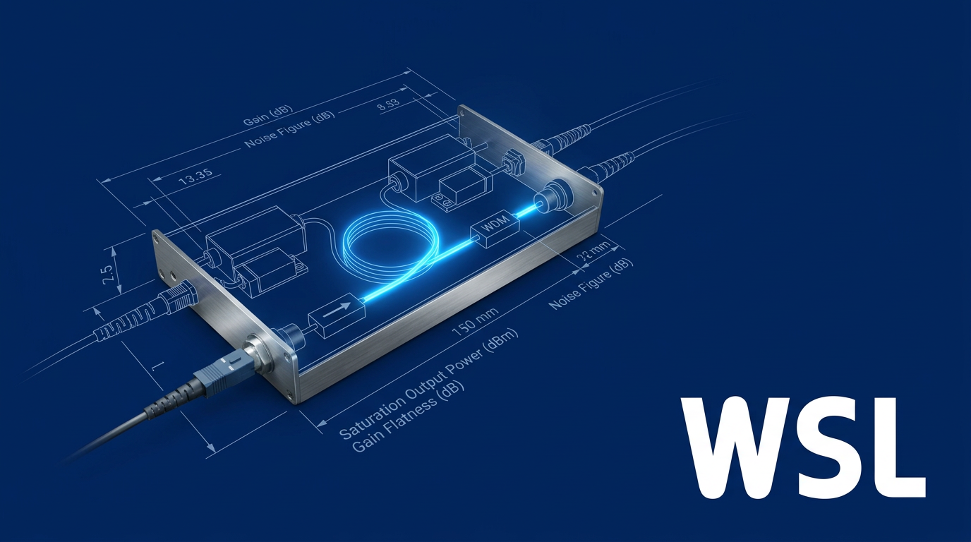
Introduction
If you've spent any time researching EDFA manufacturers, you've likely hit the same wall: plenty of product pages and supplier directories telling you what exists, but very little guidance on how to actually choose.
This guide is built for technically capable buyers who are past the awareness stage and into active evaluation — engineers, systems architects, and procurement managers who need a structured framework, not another catalogue.
It does not rank or endorse specific vendors, and it won't re-teach fundamentals you already know.
What it does offer is the kind of hard-won, application-grounded judgement that makes shortlisting rigorous and vendor conversations productive.
TL;DR
Selecting an EDFA supplier isn't about finding the highest-spec product on the market. It's about matching specification priorities to your application's functional role, then pressure-testing whether the supplier has the engineering depth and commercial maturity to back it up long-term.
This article covers:

Reading EDFA spec sheets critically
Pump architecture as a supplier signal
Matching specs to application context
Customisation depth and certifications
Red flags: manufacturer vs. reseller
What are EDFA manufacturers?
Before you can meaningfully compare suppliers, you need a clear picture of what they actually make — because an EDFA is not a commodity component, and the specification sheet alone rarely tells the full story.
An EDFA (Erbium-Doped Fiber Amplifier) is an optical amplifier that uses erbium-doped silica fibre to amplify light signals directly in the optical domain, operating across the C-band (approximately 1530–1565 nm) and, in many designs, the L-band (approximately 1565–1625 nm), without converting the signal to electrical form and back.
That absence of optical-electrical-optical (OEO) conversion is what made EDFAs transformative: from the early 1990s they displaced optoelectronic repeaters and enabled the long-haul and transoceanic fibre links that underpin modern telecommunications infrastructure.
The technology is mature and the supplier ecosystem is substantial — which means the challenge facing a procurement team today is not finding EDFA manufacturers, but distinguishing between them.
The three functional roles of an EDFA
Where an EDFA sits in the network determines which performance parameters matter most — and this is why the same device cannot be evaluated against a single universal scorecard.
- Booster Amplifier: Placed immediately after the transmitter. Primary priority is high output power; noise figure is less critical because the input signal is already strong.
- In-Line Amplifier: Placed at mid-span intervals in long-haul links. Must balance gain and noise figure; gain flatness becomes critical in multi-channel WDM systems.
- Pre-Amplifier: Placed immediately before the receiver. Lowest achievable noise figure is the primary concern; output power is a secondary consideration.
Each of these roles maps to a distinct set of specification priorities, and those priorities are expressed through a common vocabulary you will encounter throughout this guide.
The five core parameters to know are gain (dB) — the amplification added to the optical signal; output power (dBm) — the maximum optical power at the amplifier's output; noise figure (dB) — a measure of how much the amplifier degrades the signal-to-noise ratio; gain flatness — how uniformly gain is applied across the operating wavelength range; and operating wavelength range — whether the device covers C-band, L-band, or a combined C+L band.
A booster, an in-line amplifier, and a pre-amplifier may all use the same core gain medium — but their optimal specifications diverge significantly. Evaluating them on the same criteria leads to the wrong shortlist.
The supplier landscape adds another layer of complexity: it spans from large, vertically integrated telecom component manufacturers — who design and fabricate the pump lasers, erbium-doped fibre, and gain modules in-house — to specialist scientific and R&D suppliers offering high-flexibility custom configurations, to catalogue resellers who aggregate third-party components without deep engineering capability.
That spectrum is precisely why a buyer's guide exists: a directory of company names is not an evaluation framework, and the gap between a vertically integrated manufacturer and a reseller can be invisible until a project is already in trouble.
With this vocabulary in place, the natural next step is learning how to read the specification sheets that EDFA manufacturers publish — and where those sheets can mislead as much as they inform.
Reading EDFA Specification Sheets Critically
Every EDFA datasheet is designed, at least in part, to present the product favourably. The numbers are real — but without the measurement conditions that generated them, they are incomplete. A headline gain figure measured at a weak input signal is not the same as gain at operating power. A noise figure quoted without a stated input power level is not a specification; it is a starting point for a conversation. The buyers who get burned are the ones who compare headline numbers across suppliers without asking what conditions those numbers were measured under.
Gain: Small-Signal vs. Saturated
Small-signal gain is measured at a weak input signal — it represents the maximum amplification the device can achieve when the amplifier is not being asked to do real work. Thorlabs, for instance, specifies small-signal gain at −20 dBm input power, where their EDFA100 series achieves >30 dB and the higher-power EDFA300 series reaches >40 dB.
Saturated gain — the gain the amplifier actually delivers at its rated output power — is substantially lower, and this is the figure that governs real system performance. Both values appear on datasheets, and they are not interchangeable.
The practical risk is straightforward: a buyer comparing a small-signal gain from one supplier against a saturated gain from another is making an apples-to-oranges error. When you see a headline gain number, your first question should be: "At what input power was this measured?"
Saturated Output Power: The Primary Booster Metric
Saturated output power is the maximum power the amplifier can deliver into the fibre — and for booster amplifiers, it is the specification that matters most. The threshold commonly cited for booster-grade performance is 20 dBm or more, with high-power variants reaching beyond 24.5 dBm or 27 dBm for cladding-pumped designs.
For pre-amplifier selection, saturated output power is a secondary concern — noise figure dominates there. Prioritising output power when evaluating a pre-amplifier, or prioritising noise figure when evaluating a booster, reflects a misunderstanding of what each amplifier role is optimised for.
Noise Figure: The Most Misrepresented Parameter
Quantum optics sets a hard floor: for any phase-insensitive optical amplifier operating at high gain, the minimum achievable noise figure is 3 dB. This is not a design target — it is a physical limit. Practical EDFAs typically achieve 4–6 dB, with the best pre-amplifier designs approaching the lower end of that range.
The critical caveat that datasheets frequently omit: noise figure varies with input power level, so a quoted noise figure is only meaningful when the measurement input power is stated alongside it. A headline noise figure without that condition is an incomplete specification.
The question to put to any supplier is: "At what input power was this noise figure measured, and can you provide a noise figure vs. input power curve?" A supplier who cannot produce that curve is asking you to accept a single data point in place of a characterisation.
It is also worth noting that pump wavelength choice influences the achievable noise figure — a topic the next section covers in depth when examining what pump laser architecture reveals about a manufacturer's engineering decisions.
Gain Flatness: The DWDM Differentiator
The erbium gain spectrum is not uniform across the C-band. Left untreated, different wavelength channels receive different levels of amplification — a manageable nuisance in single-channel systems, but a compounding problem across cascaded amplifier spans in multi-channel DWDM deployments.
Gain-flattening filters (GFFs) are used to equalise channel powers, and commercial C-band EDFAs with GFFs typically achieve gain flatness in the range of 1–1.5 dB peak-to-peak across the operating band. Engineering-depth designs have demonstrated 0.2 dB over a 14 nm window, though that represents a deliberate optimisation target rather than a commodity specification.
The buyer's caveat here mirrors the noise figure problem: a flatness specification is only meaningful at a stated operating power level. Gain flatness at one input power can look meaningfully different at actual deployment conditions — ask suppliers to provide flatness data at the power levels your system will use, not at a single convenient test point.
Operating Wavelength Range: Beyond the Band Label
Most EDFAs operate in the C-band (approximately 1530–1565 nm). L-band amplifiers, covering approximately 1565–1625 nm, are used where additional capacity is required in dense DWDM systems. The band label itself is not the check — coverage uniformity across that band is.
A supplier claiming "C-band coverage" may not amplify uniformly across the full 1530–1565 nm window. The practical step is to confirm the amplifier covers the specific ITU channels in your deployment plan and to ask for gain flatness data across that actual channel set — not just a nominal band label on a product page.
Polarisation-Dependent Gain: The Coherent Caveat
Polarisation-dependent gain (PDG) describes the variation in gain with the polarisation state of the input signal. For most standard EDFA applications it is a minor consideration, but it becomes significant in coherent transmission systems and polarisation-sensitive sensing applications.
Telecom-grade amplifiers typically specify PDG below 0.5 dB — a figure confirmed on real commercial datasheets, including Thorlabs' EDFA100 series and multiple FS.com DWDM EDFA products. PDG is frequently omitted from standard specifications; buyers in coherent or sensing applications should request it explicitly.
The data table below summarises the key specification benchmarks across all six parameters.
| Parameter | Physical / Theoretical Limit | Typical Commercial Range | Primary Relevance |
|---|---|---|---|
| Small-signal gain | Limited by ASE above ~40 dB | 30–40 dB (core-pumped) | All roles; verify measurement input power |
| Saturated output power | Architecture-dependent | ≥20 dBm (booster threshold); >24.5–27 dBm (high-power) | Booster amplifiers (primary metric) |
| Noise figure | 3 dB (quantum limit, high gain) | 4–6 dB (practical devices) | Pre-amplifiers (primary metric) |
| Gain flatness | Design-dependent | 1–1.5 dB peak-to-peak (C-band, with GFF) | DWDM / multi-channel systems |
| Operating wavelength | Erbium transition: ~1530–1625 nm | C-band: 1530–1565 nm; L-band: 1565–1625 nm | All roles; verify channel-level coverage |
| Polarisation-dependent gain | Near 0 dB (ideal PM design) | <0.5 dB (telecom-grade) | Coherent and polarisation-sensitive systems |
Comparison of EDFA key performance parameters: quantum or physical limits vs. typical commercial values, to give buyers a concrete reference frame for evaluating datasheets.
The table makes one pattern immediately visible: the parameters that matter most depend entirely on the amplifier's functional role. A booster with a noise figure of 6 dB is not a poorly specified amplifier — it is a correctly specified booster, where saturated output power is the governing metric. Applying the wrong evaluation lens to any row in this table leads to bad shortlist decisions.
It also reinforces the measurement-condition discipline: every figure in the "typical commercial range" column is only as useful as the test conditions that produced it. The quantum limit for noise figure is unconditional; the commercial figures are not.
Comparing a booster's saturated output power against a pre-amplifier's noise figure as equivalent quality signals is a fundamental evaluation error. Each amplifier role optimises for a different primary parameter — the best EDFA is always the one best matched to its deployment function, not the one with the most impressive headline number.
Specification sheets tell you what a supplier chose to measure and how they chose to present it. The next layer of evaluation goes deeper: the pump laser architecture behind those numbers often reveals more about a manufacturer's engineering depth than any figure on the datasheet does.
Pump Laser Architecture as a Supplier Evaluation Signal
Pump architecture is one of the clearest places in EDFA design where genuine engineering depth becomes visible — and where the gap between a true manufacturer and a catalogue reseller is hardest to hide.
The spec sheet tells you what an EDFA achieves; the pump architecture explains why it achieves it, and whether that performance is built on a foundation a serious buyer should trust.
980 nm vs. 1480 nm: The Foundational Design Choice
Every EDFA designer begins with the same choice: which pump wavelength to use.
980 nm pumping excites erbium ions via an intermediate energy level, from which they rapidly transfer to the upper laser level — a process that allows very high population inversion and, consequently, the lowest achievable noise figure and highest gain efficiency.
The trade-off is power conversion efficiency: because the pump photon energy is significantly higher than the signal photon energy, the quantum defect is large, meaning a meaningful fraction of pump power is lost as heat rather than converted to signal gain.
1480 nm pumping works differently — it directly excites erbium ions into the upper laser level, which means stimulated emission by the pump light itself limits the achievable population inversion.
That constraint raises the noise figure relative to 980 nm forward pumping, but the smaller quantum defect produces better power conversion efficiency: peer-reviewed data shows power conversion efficiencies of approximately 50% at 980 nm and up to 80% at 1480 nm.
This is why the two parameters you evaluated in §4 — noise figure and output power — look so different inside a pre-amplifier versus a booster: the pump wavelength choice is the primary engineering lever driving that difference.
Hybrid Pumping: Getting Both in One Product
High-performance multi-stage amplifiers — particularly those targeting DWDM and long-haul telecom deployments — frequently combine both wavelengths in a hybrid pumping architecture.
The first stage uses 980 nm to establish low noise figure at the pre-amplifier; the second or booster stage uses 1480 nm to reach high saturated output power — a combination that neither wavelength optimises alone.
Published amplifier data confirms that hybrid 1480/980 nm designs have achieved output powers in the range of +20 dBm while preserving low noise figure at the input stage — performance that a single-wavelength design cannot match at both ends simultaneously.
The buyer-facing implication is direct: ask any supplier whether their high-power products use hybrid pumping, and ask them to explain the design rationale behind the stage split.
A manufacturer with genuine engineering depth will answer this fluently; a reseller sourcing finished modules from a third party will not be able to.
Wavelength Stabilisation: FBGs and the Cooled vs. Uncooled Question
Pump emission wavelength drifts with temperature — and for 980 nm pumping in particular, the erbium absorption band is narrow enough that unconstrained drift degrades amplifier efficiency meaningfully.
The standard solution is a fibre Bragg grating (FBG) placed in the pump laser's output fibre, which acts as a wavelength-selective mirror that locks emission to the grating's reflection wavelength regardless of the laser diode's free-running drift.
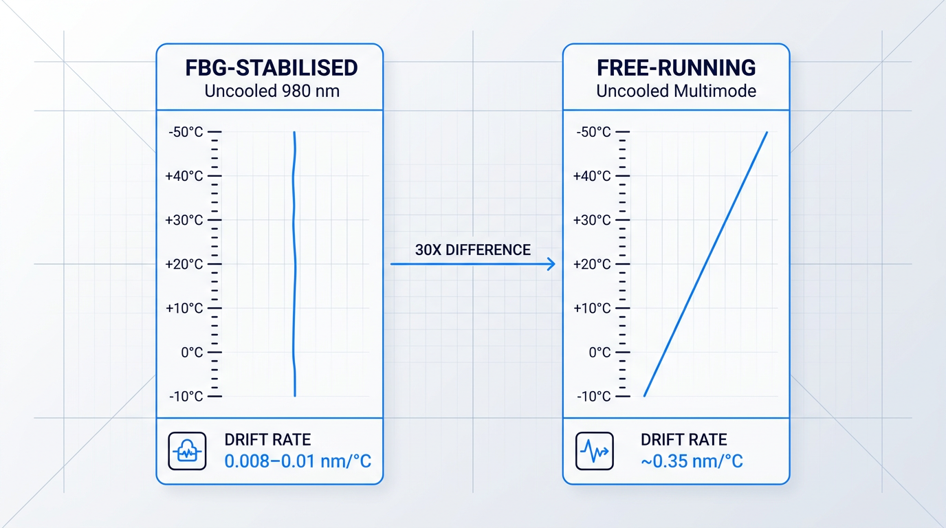
The performance difference between FBG-stabilised and unstabilised modules is substantial: FBG-locked uncooled 980 nm pump modules from leading manufacturers specify wavelength temperature dependence of 0.008–0.01 nm/°C, while free-running uncooled multimode pump lasers exhibit drift of approximately 0.35 nm/°C — more than 30 times greater.
The second stabilisation lever is the thermoelectric cooler (TEC): cooled pump modules use a Peltier element to hold the laser diode at a fixed internal temperature — typically 25°C — independent of ambient conditions, providing tight wavelength control and enabling higher drive currents and output powers.
Uncooled pump modules eliminate the TEC entirely, reducing power consumption, physical size, and module complexity — but they rely on FBG stabilisation alone to manage wavelength drift, and their output power and operating temperature range are constrained by the absence of active thermal management.
In practice, 1480 nm pump modules are almost universally cooled, because the higher drive currents required at that wavelength generate more heat than passive management can handle reliably across a wide temperature range.
When evaluating a supplier, ask specifically: are their pump modules cooled or uncooled, what is the wavelength stability specification across the operating temperature range, and what are the reliability implications of that choice for your target deployment environment?
Pump Laser Reliability: The Supply Chain Signal That Matters Most
The pump laser is the primary wear component in any EDFA — the erbium-doped fibre itself is essentially passive and does not degrade under normal operating conditions.
This means pump laser longevity is the primary determinant of EDFA operational lifetime, and a supplier's transparency about pump laser reliability data is one of the most commercially meaningful signals available to a buyer.
A supplier who cannot provide pump laser MTBF figures — or deflects the question — is signalling limited visibility into their own supply chain. For telecom and defence deployments with multi-year operational lifespans, this is a disqualifying red flag, not a minor gap.
Industry reliability data for 980 nm uncooled pump modules used in telecom-grade EDFAs specifies total module failure rates below 500 FIT (failures per 10⁹ hours of operation), with actual rates often lower; submarine-grade pump lasers are qualified to even tighter targets, with ITU-T G.Suppl.41 citing a typical failure rate of 25 FIT for submarine laser pumps.
A second and equally important question is whether the supplier manufactures pump lasers in-house or sources them from a third party.
Vertical integration — designing and manufacturing pump laser chips internally — is a meaningful signal of both quality control depth and supply chain resilience: the supplier controls the epitaxial growth, chip fabrication, and qualification process rather than depending on a third party's decisions, lead times, and end-of-life announcements.
A supplier sourcing pump lasers externally is exposed to that third party's quality variability and component lifecycle decisions — a risk that compounds over the multi-year operational lifespans typical of telecom infrastructure.
Ask suppliers directly: do you manufacture pump laser chips in-house, or do you source them externally? If externally, from which supplier, and what is your incoming qualification and screening process?
Pump Redundancy in High-Reliability Deployments
For deployments where the EDFA cannot be accessed after installation — submarine cables, remote repeater sites, and similar environments — pump redundancy is not an optional enhancement; it is a core reliability requirement.
A single pump laser failure in a non-redundant design causes complete loss of amplification for the affected fibre path; redundant architectures allow continued operation, typically at reduced output or with degraded noise figure, until the failed pump can be addressed.
The baseline architecture pairs two pump lasers per EDFA direction, with their outputs combined through an optical coupler so that either pump alone can sustain amplifier operation if the other fails — a configuration documented in submarine repeater engineering literature as maintaining transmission path characteristics through a single pump failure.
More sophisticated configurations extend this further: a pooled architecture known as pump farming cross-connects a pool of pump lasers to multiple EDFA gain stages through a coupler matrix, so that the failure of several individual pump lasers does not disable any single amplifier direction.
ITU-T G.Suppl.41 notes explicitly that pump redundancy is the standard approach to meeting submarine amplifier reliability targets, and that a single pump failure will always induce some output power and noise figure degradation — making the failover behaviour (graceful degradation versus hard cutover) a meaningful specification point.
When evaluating suppliers for high-reliability applications, ask whether redundant pump configurations are available, what the failover behaviour is, and whether this is a standard catalogue option or requires a custom engineering engagement.
Understanding pump architecture gives you a sharper lens for supplier evaluation — but which architectural features matter most depends heavily on where and how your EDFA will be deployed, which is exactly what the next section addresses.
Application Context and Specification Priorities
The specifications on a datasheet do not change based on where the amplifier is deployed — but the evaluation framework absolutely should. A buyer who optimises for noise figure when procuring a CATV booster, or who prioritises saturated output power when selecting an in-line amplifier for a long-haul DWDM chain, will make a poor purchase even if they read every number correctly. Application context is the primary filter: it determines which parameters matter, which are secondary, and what questions are worth raising with a supplier.
DWDM Long-Haul and Submarine Networks
This is the most demanding EDFA application context, and the dominant parameters are noise figure and gain flatness — not output power. In a cascaded in-line amplifier chain spanning dozens of spans, small per-amplifier noise figure deficiencies and gain tilt accumulate: a marginal deficit that looks acceptable in a single-unit test becomes a system-level problem when multiplied across an entire link.
Gain flatness across the full C-band — and L-band where the system is designed for extended capacity — is a meaningful differentiator between suppliers in this context, not a secondary specification.
For deployments in ROADM-based networks with dynamic channel add/drop, ask suppliers specifically about transient suppression capability: rapid changes in channel loading create power transients that can saturate or destabilise downstream amplifiers, and not all EDFA designs handle this equally.
CATV and FTTx Distribution
The priority order flips entirely in CATV and FTTx booster applications. Here, saturated output power is the primary metric: the amplifier is driving signal into a passive splitting network serving many subscribers, and raw output power determines how many subscribers can be reached from a single amplifier.
Noise figure is less critical at the booster stage because the input signal power is already high — the carrier-to-noise ratio of the system is largely set earlier in the chain, and the booster's contribution to noise is proportionally smaller. What matters is how much power can be delivered into the distribution network.
Standard core-pumped EDFA architectures are limited in how much output power they can deliver. According to RP Photonics, core-pumped EDFAs are typically limited to around 500 mW (27 dBm) of output power, while configurations requiring higher output use cladding-pumped designs with double-clad Er/Yb co-doped fibre — which allow high-power multimode pump light to be launched into an inner cladding rather than the core, enabling watt-level output from a single pump diode.
Multi-port output configurations are also common in CATV deployments, allowing a single amplifier to feed multiple distribution branches directly — ask suppliers whether their high-power products support this, and confirm the output power specification per port rather than aggregate.
SDH/SONET and Metro Networks
Metro deployments occupy a more moderate performance band: neither noise figure nor output power is pushed to extremes. What shifts the evaluation in this context is scale — metro networks involve many amplifier sites, often in constrained rack environments, so cost per unit and form factor density start to rival pure optical performance as differentiating factors.
Automatic gain control (AGC) is a capability worth prioritising here. Metro networks frequently operate with dynamic channel counts as traffic is added and dropped; without AGC, per-channel power levels fluctuate with every change, creating instability across the network. Ask suppliers whether AGC is standard or an option, and what the control loop response time is.
Management interface capability — SNMP, Telnet, RS-485 — also becomes a practical procurement consideration at metro scale, where many units must be monitored and managed remotely from a network operations centre.
Fibre Sensing: DAS, DTS, and LIDAR
Fibre sensing is a specialist context with requirements that diverge sharply from telecom applications. The primary need is a low-noise pre-amplifier with wide dynamic input range — sensing systems typically work with weak backscattered signals, and the amplifier's noise performance directly determines the system's detection sensitivity.
Many sensing techniques are polarisation-sensitive: coherent distributed acoustic sensing (DAS), fibre-optic gyroscopes, and interferometric sensors all depend on maintaining a stable polarisation state through the amplifier. For these applications, polarisation-maintaining (PM) fibre configurations are a functional requirement, not a preference — PM fibre preserves the linear polarisation of light launched into it by introducing strong, well-defined internal birefringence that prevents coupling between polarisation modes.
Time-domain sensing systems — OTDR-style DTS, LIDAR ranging, and BOTDA-based distributed sensors — interrogate the fibre with optical pulses rather than continuous-wave signals. Pulse amplification capability is a distinct operating mode from CW amplification and should be confirmed explicitly with any supplier being evaluated for these applications.
Scientific and R&D Deployments
R&D buyers typically have the widest tolerance for specification variation across the six application contexts, but the highest requirements for controllability and interface flexibility. Benchtop form factors with front-panel control and computer interfaces are standard in this segment; the ability to adjust gain, output power, and operating mode programmatically is often as important as the optical performance itself.
PM output, pulse amplification capability, and C+L band coverage are common requirements for research applications — but the specific combination varies by experiment, which is why suppliers who explicitly target this segment, such as Keopsys, tend to offer broad configurability and application engineering support alongside their standard product lines.
Sample or demonstration unit availability matters more in this context than in production deployments: R&D buyers need to characterise the amplifier against their specific experimental conditions before committing to a purchase, and a supplier who can support that evaluation process is genuinely more valuable than one who cannot.
Defence and Aerospace
In defence and aerospace procurement, the evaluation framework shifts away from optical performance parameters almost entirely. The dominant requirements are environmental qualification — including MIL-STD-810 testing for temperature, shock, vibration, and humidity extremes — and, for space applications, radiation hardening: erbium-doped fibres used in space-qualified EDFAs are specifically selected and tested for radiation-induced gain degradation, as confirmed by published SPIE proceedings on miniaturised CubeSat EDFA development.
Supply continuity is the other dominant procurement driver. Defence programmes have multi-decade lifespans, and the DoD's DMSMS (Diminishing Manufacturing Sources and Material Shortages) framework explicitly addresses the risk of component obsolescence across long programme lifecycles. A supplier who cannot offer long-term supply agreements, documented change control, or a credible component availability roadmap represents a programme risk that is independent of how well the amplifier performs optically.
The 'best' EDFA is always relative to the deployment. Noise figure dominates in long-haul DWDM; saturated output power dominates in CATV distribution; environmental qualification and supply continuity dominate in defence. Applying the wrong framework — even with the correct specification data — leads to poor purchasing decisions.
With application context established as the primary evaluation filter, the next layer of the procurement decision is physical: which form factor fits the deployment environment, the integration constraints, and the volume requirements of the programme.
EDFA Form Factors: Matching the Package to Deployment
A procurement that gets the performance parameters exactly right can still fail at integration — because the wrong physical package for the deployment environment creates problems that no amount of gain or noise figure optimisation will fix.
Form factor selection is not a preference; it is a consequence of deployment context, integration architecture, and lifecycle management requirements. The same application logic that determined whether noise figure or output power was your primary performance metric also points directly to which packaging tier is appropriate.
Benchtop Instruments
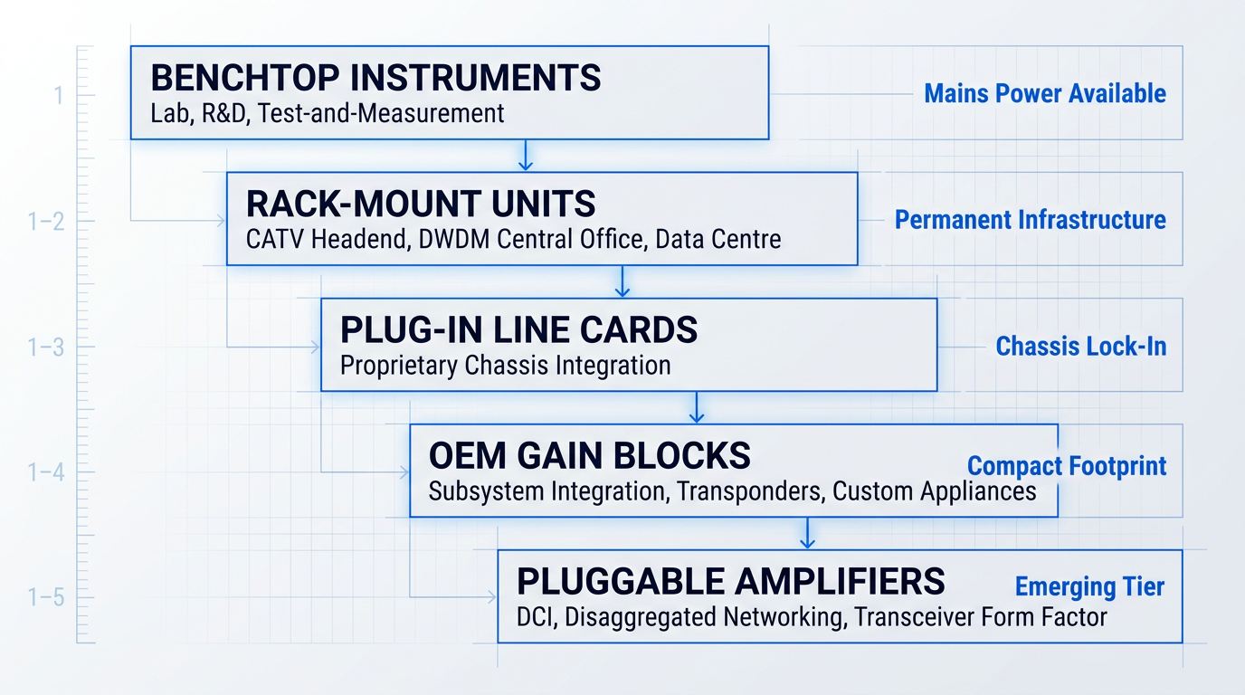
Benchtop EDFAs are self-contained instruments designed for laboratory, R&D, and test-and-measurement environments where mains power is available and manual interaction is part of normal operation.
Thorlabs's EDFA100 and EDFA300 series are representative examples: both offer front-panel controls, a display showing pump current and temperature status, and remote control via USB 2.0, with software drivers available for automated test integration.
The EDFA300 series additionally supports three operation modes — automatic current control (ACC), automatic power control (APC), and automatic gain control (AGC) — accessible through the front panel or a command-line interface over USB, making it straightforward to incorporate into automated test sequences.
Keopsys's CEFA-C series covers a similarly broad range of scientific applications, with benchtop units controllable from the front panel or via RS232, USB, or RJ45 interfaces depending on the model, and OEM module variants available for the same optical designs.
The key evaluation questions at this tier are interface compatibility with existing lab control systems, availability of software drivers (LabVIEW and Python support vary by supplier), and whether the unit can be recognised as a serial port or integrated into a PXIe chassis for automated measurement workflows.
Operating temperature range is worth checking here too: the Thorlabs EDFA100 series specifies 15–35°C and the EDFA300 series 15–30°C, which is appropriate for a controlled laboratory but may not suit a field test environment.
Rack-Mount Units for Permanent Infrastructure
The CATV headend and DWDM central office contexts covered in the previous section point naturally toward rack-mount chassis units — 1U to 4U, 19-inch rack-compatible enclosures designed for permanent installation in telecom facilities and data centre interconnect sites.
This tier typically offers higher output power configurations, SNMP and CLI management, front-panel status indicators, and redundant power supply options — all of which matter when the amplifier is an always-on element of a production network.
Evaluation questions to bring to a supplier at this tier: which SNMP version is supported, whether out-of-band management is available, whether fan redundancy is provided, and whether multi-pump redundancy is an option for high-availability deployments.
Airflow direction (front-to-back versus side-to-side) is a rack-level integration detail that is easy to overlook during procurement and difficult to resolve post-installation, particularly in high-density facilities where adjacent equipment constrains airflow paths.
Plug-In Modules and Line Cards
Where the chassis is the operational environment — rather than a standalone rack — plug-in line cards are the appropriate tier, designed to slot into a specific proprietary platform and integrate with its management fabric.
Cisco's EDFA2 line card for the NCS 1014 platform is a representative example: a fully variable gain amplifier card integrating both a pre-amplifier and booster, along with an optical supervisory channel (OSC), a pluggable OTDR module, and a wavelength blocker for per-channel equalisation — all managed through Cisco IOS XR CLI, OpenConfig, and streaming telemetry.
For CATV headend deployments, the Cisco Prisma II HD EDFA modules take a similar approach: the modules slot into a Prisma II or Prisma XD chassis, with up to 16 HD EDFA modules per XD chassis, managed via Local Craft Interface or the Intelligent Communications Interface Module (ICIM).
The critical evaluation questions at this tier are chassis lock-in implications — a module designed for one vendor's chassis management API will not transfer to another platform — and whether the supplier supports the specific chassis management interface version your network operations team uses.
Upgrade path within the chassis ecosystem is also worth mapping before procurement: the NCS 1014, for instance, supports field-replaceable line cards with redundant power supply units, but the chassis itself constrains which card generations are compatible.
OEM Modules: Compact Gain Blocks
When the EDFA is a subsystem inside a larger instrument, transponder, or custom network appliance, the appropriate form factor is a compact OEM gain block — a sealed metal enclosure with no user interface, where the host system provides power, thermal management, and digital control.
Evaluation priorities at this tier: confirm the electrical connector type and mechanical footprint against your host system's physical constraints, verify which control modes are available (ACC, APC, AGC), check whether output power monitoring and pump current readback are supported, and establish the thermal interface requirements before committing to a mechanical design.
Pluggable Amplifiers: An Emerging Tier
For data centre interconnect and disaggregated networking applications where amplification must fit within the density constraints of a pluggable transceiver, a new tier has emerged: EDFA amplification in pluggable form factors.
Coherent's FlexSOM EDFA is a representative example — C-band (and L-band variant) amplification packaged within a CFP transceiver form factor, targeting DCI and disaggregated network deployments where fitting amplification inside the transceiver module eliminates the need for a separate external amplifier or line card.
Coherent's Pluggable Open Line System (POLS) extends this further, integrating dual EDFAs (booster and pre-amplifier) in QSFP and OSFP form factors with a CMIS management interface, enabling direct plug-in to a router or switch for point-to-point spans.
This tier is not yet the default for telecom or enterprise deployments: it is most relevant where DCI density requirements or disaggregated architecture mandates drive the decision, and buyers should evaluate power dissipation within the pluggable thermal envelope and CMIS compliance with the host platform's pluggable management framework before specifying it.
Thermal Management: A Cross-Cutting Evaluation Dimension
Thermal management is not a form factor tier in itself, but it is an evaluation dimension that applies differently at every tier — and it is one that buyers consistently underweight until it causes a post-delivery problem.
For OEM gain block modules, the integrator is entirely responsible for thermal management: heat sink design, chassis thermal contact, and airflow path are all the host system's problem, not the supplier's.
Rack-mount units include internal fans as standard, but buyers should verify fan redundancy, confirm the airflow direction matches the rack environment, and check whether the unit is rated for operation in high-ambient-temperature locations such as outdoor cabinets or non-air-conditioned facilities.
Benchtop units are typically designed for controlled laboratory conditions — the Thorlabs EDFA300 series, for instance, specifies a 15–30°C operating temperature range — so buyers planning to use them in non-standard environments should verify the thermal envelope explicitly.
A unit rated to operate at 70°C ambient may only achieve that at reduced output power. Always request the supplier's thermal derating curve — showing how output power and performance degrade as ambient temperature rises — not just a single maximum ambient figure. These are different specifications, and confusing them leads to undersized thermal designs.
Suppliers will rarely volunteer derating curves unprompted; the buyer must ask for them explicitly, and treat their absence as a gap in the supplier's documentation — not an indication that derating does not occur.
Once you have identified which form factor tier your deployment requires and mapped the thermal constraints, the natural next question is whether the supplier can adapt that form factor to your specific integration requirements — custom mechanical footprints, particular connector configurations, or specific control interfaces — which is the focus of the following section.
Customisation Depth as a Supplier Engineering Signal
Specification sheets tell you what a supplier ships. Customisation questions tell you whether they actually engineer. A catalogue reseller can match your headline specs perfectly and still be unable to adapt a single parameter to your system's requirements — because they are selecting from fixed configurations, not designing to your needs.
This is the test that separates genuine EDFA manufacturers from assemblers and resellers: ask them to modify something. The breadth and confidence of their response is more revealing than any datasheet figure.
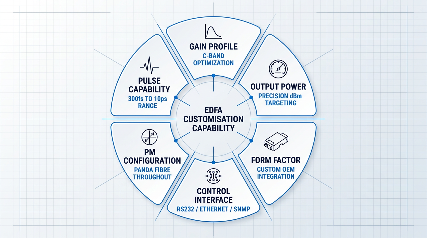
Six Customisation Dimensions Worth Testing
The following capabilities are not exotic requests — they are routine requirements for integration-focused buyers. A supplier who cannot address most of them is constrained in ways that will surface as problems once a project is underway.
- Gain profile engineering: Can the supplier optimise the gain spectrum for a specific C-band sub-band, or achieve flat gain across C+L simultaneously? This requires in-house fibre and component knowledge, not catalogue selection.
- Output power configurability: Can they target a precise dBm figure to match your link budget, rather than pointing you at the nearest fixed tier? Requires genuine understanding of pump power, fibre length, and gain dynamics.
- Form factor adaptation: Can they produce a custom OEM module footprint, specific connector configuration, or bespoke mechanical interface for integration into your chassis? A standard enclosure is a constraint, not a solution.
- Control interface flexibility: Can they implement RS232, Ethernet, SNMP, or other protocols, and provide software drivers for automated test environments? A fixed front-panel interface is a poor fit for R&D integration.
- Polarisation-maintaining configurations: Can they offer PM fibre throughout the signal path? A hard requirement for coherent communications, fibre sensing, and interferometry — non-negotiable for those applications.
- Pulse amplification capability: Can they configure for pulsed operation, with defined peak power limits and pulse duration ranges? Relevant for LIDAR, time-domain sensing, and scientific amplification.
Taken together, these six dimensions form a coherent picture of supplier depth. A supplier who can engage confidently on all of them has genuine in-house engineering capability across fibre design, component selection, mechanical integration, firmware, and optics.
A supplier who deflects, offers only catalogue alternatives, or cannot discuss the underlying design trade-offs is almost certainly reselling or assembling from fixed-configuration components — and their ability to support a complex integration project is correspondingly limited.
Control Interfaces and Protocol Support
For R&D and instrumentation buyers, control interface flexibility is often the deciding factor — and it is frequently underweighted in early supplier conversations. The RP Photonics fibre amplifier buyer's guide specifically flags computer interface as a named selection criterion, alongside optical connectors and form factor.
Confirmed interface options across the market include RS232 on benchtop and standard EDFA lines (with optional TCP/IP Ethernet on some models), and SNMP over RJ45 on the Keopsys CEFA-C-HG series. OEM module electrical interfaces often differ — some OEM modules use MIL socket or DB25 connectors rather than RS232 — so buyers integrating gain blocks into larger systems should verify the specific electrical interface against their integration requirements, not assume it matches the benchtop product line.
Polarisation-Maintaining and Pulsed Configurations
Polarisation-maintaining (PM) configurations are a hard requirement for a meaningful subset of applications: coherent communications, fibre interferometers, fibre-optic gyroscopes, and certain sensing architectures. PM fibre preserves the linear polarisation state of the input signal by maintaining strong, well-defined internal birefringence throughout the signal path.
Not all suppliers can offer PM throughout the full amplifier chain. Dedicated high-power PM EDFA compact modules are available with output power from +30 to +34 dBm and a minimum polarisation extinction ratio of 20 dB, using PM 1550 Panda fibre. Keopsys similarly offers PM options on their CEFA-C-HG high-gain series. A supplier who cannot offer PM is simply not competitive for those use cases.
Pulse amplification is a distinct and more specialised capability. For LIDAR, time-domain sensing, and scientific applications, the relevant questions are peak power ceiling and supported pulse duration range — not the CW output power figure on the standard datasheet. As an illustration of what specialist capability looks like, Keopsys's PEFA-SP-C series supports pulse widths from 300 femtoseconds to 10 picoseconds with up to 1 kW peak power, while their PEFA-LP-C/EOLA series targets longer pulses of 200 to 400 ns with up to 110 µJ pulse energy. A general telecom component supplier will typically have no equivalent offering.
OEM Commercial Terms: MOQ and NRE
Customisation is commercially viable only above certain volumes. Before investing engineering time in a customisation discussion, buyers should ask directly about MOQ (minimum order quantity) thresholds for bespoke configurations and whether NRE (non-recurring engineering) charges apply.
NRE is a legitimate cost of custom development — it covers the engineering time required to design, prototype, and validate a configuration that does not exist in the catalogue. What varies between suppliers is whether NRE is charged as a flat upfront fee or amortised across the order volume. Neither model is inherently better; what matters is that you understand it before the project starts, not after the first invoice.
EDFA vendors do not publish MOQ or NRE figures openly — these are commercial variables negotiated per project. The practical implication is that you need to raise these questions explicitly in early supplier conversations, rather than assuming customisation is available at any volume or at no additional cost.
A supplier who can discuss gain profile engineering, PM fibre options, control protocol requirements, and NRE terms with confidence is demonstrating in-house engineering depth. One who redirects every question back to their catalogue is telling you something equally important.
Application Engineering Support
The final and perhaps most revealing test of supplier maturity is whether they offer application engineering support — simulation data, reference designs, or direct consultation for integration projects — or whether their post-sale engagement ends at shipping a module with a datasheet.
For complex integrations, the absence of application engineering support is a genuine risk signal. An amplifier that performs to spec in isolation can still fail to meet system requirements if the integration assumptions are wrong — and a supplier without application engineering capability cannot help you diagnose or resolve that gap.
Ask specifically: does the supplier provide link budget simulation support? Do they offer reference designs for common integration architectures? Is there an applications engineer you can speak with before the purchase order, not just after? The answers will tell you whether you are buying a component or entering a working engineering relationship.
With engineering depth assessed through these customisation and support questions, the next layer of supplier qualification is compliance: the certifications that distinguish suppliers operating to documented process standards from those who do not.
Custom EDFAs Built to Your System Requirements
Not every application fits a catalogue product. Our EDFAs are engineered to specification — gain, output power, form factor, and wavelength range adapted to your system from the ground up.

Certifications: the compliance baseline every supplier must clear
By this point in your evaluation, you have a picture of what a supplier can do — their engineering depth, customisation capability, and application fit. The next question is what they must prove. Certifications are not differentiators; they are the floor. A supplier who holds the relevant certifications has simply cleared the entry bar. One who cannot demonstrate them for their target market segment has failed the evaluation before it has properly begun.
The five compliance areas below map to the screening questions every serious EDFA procurement should run through before a supplier reaches the shortlist.
- Telcordia GR-468: The primary reliability qualification for telecom optoelectronics, covering Temperature Cycling, Unbiased Damp Heat, High Temperature Storage, and Accelerated Life Test. Telcordia specifications require components to be reliable in the field for more than 20 years — a supplier who has not subjected their products to this discipline has not demonstrated that they can meet that bar. For carrier-class deployments, GR-468 qualification is a prerequisite, not a bonus.
- CE Marking and RoHS: Non-negotiable for products placed on the EU market. CE marking attests conformity with applicable EU directives; RoHS restricts ten hazardous substances including lead, cadmium, and mercury in electrical and electronic equipment. Their absence disqualifies a supplier from European procurement. Buyers in other markets should verify applicable regional equivalents independently.
- MIL-Spec and Space Qualification: Defence and aerospace applications require environmental testing well beyond commercial norms — extended temperature ranges, vibration and shock testing, and radiation hardening for space missions. Commercial certifications alone do not qualify a product for these environments. Ask specifically about MIL-PRF or MIL-STD experience and verified track record.
- ISO 9001: Signals that the supplier operates a documented, audited quality management system. Per ISO's own supply chain guidance, ISO 9001 provides confidence that a supplier can consistently deliver conforming goods — but it is not a product performance certification. Particularly relevant for OEM and high-volume procurement where batch-to-batch repeatability matters.
- IEC 60825 Laser Safety: Suppliers should provide IEC 60825-1 product classification documentation. At higher output powers, IEC 60825-2 hazard level assessment at accessible locations applies, and Automatic Power Reduction (APR) mechanisms are required to prevent hazardous exposure during fiber breaks or system restarts. Buyers integrating EDFAs into larger systems need this documentation for their own system-level safety case.
Taken together, these certifications define the compliance baseline for any credible EDFA manufacturer. A supplier who can produce current documentation across all relevant categories for their target market has demonstrated the minimum operational discipline required. One who cannot — or who is vague about which standards apply to their products — warrants serious scrutiny before any further evaluation proceeds.
Passing the relevant certification bar tells you a supplier is qualified to be evaluated — not that they are good. The differentiation between suppliers comes from engineering depth, customisation capability, and procurement terms. Missing certifications disqualify; having them simply means the real evaluation can begin.
With the compliance baseline established, the next layer of supplier evaluation moves into territory that specification sheets and certification documents never cover: the commercial and operational factors that determine whether a supplier relationship will hold up across a multi-year deployment.
Procurement Factors the Specification Sheet Never Covers
A specification sheet tells you what an EDFA can do on the day it ships. It tells you nothing about whether the supplier can support a five-year deployment, replace a failed unit within an acceptable timeframe, or guarantee that the pump laser inside it will still be available when you need a spare in year three.
The technical evaluation framework covered in the preceding sections is necessary — but it is only half the picture. Lifecycle cost and supply chain resilience are the other half, and they are almost entirely absent from supplier datasheets and from the broader landscape of EDFA procurement guidance.
The seven criteria below are what a seasoned buyer asks about before signing — not as a formality, but because these are the factors that determine whether a supplier relationship succeeds or breaks down over a multi-year operational horizon.
- Lead times, committed in writing: Standard catalogue and custom configuration lead times can differ by months. Ask for committed dates, not indicative estimates, and enquire about buffer stock and framework agreements.
- Minimum order quantity: Catalogue units typically carry an MOQ of one; custom configurations usually require higher volumes. Confirm the threshold before investing engineering time in a customisation discussion.
- Warranty terms and rectification: Warranty periods vary considerably across the supplier landscape. Ask for the warranty duration and the committed rectification window in writing before placing any order.
- Repair and recalibration support: Ask whether in-warranty and post-warranty repair services are offered, whether calibration certificates are provided, and what the typical turnaround time for a repair is.
- Long-term component availability: Pump laser degradation is the primary EDFA failure mode. Confirm the supplier's component sourcing strategy, in-house pump laser capability, and end-of-life notification policy.
- Reference customers and deployment history: A mature supplier should be able to provide reference customers in comparable application contexts. This is standard due diligence, not an aggressive demand.
- Annual maintenance contract availability: For research institutions and government buyers, post-warranty AMC covering preventive maintenance, priority repair response, and calibration is often a formal procurement requirement.
Taken individually, any one of these criteria might seem like a secondary concern relative to gain flatness or noise figure. Taken together, they form a picture of whether a supplier is genuinely set up to support institutional or production-grade buyers over the long term.
Consider lead times first. For a production deployment where a schedule slip carries downstream costs, an "indicative" lead time from a sales team is not a procurement commitment. What matters is a written, contractual delivery date — and, for volume buyers, whether the supplier can offer a framework agreement that reserves capacity or holds buffer stock against forecast demand.
The minimum order quantity question is one of the most practically important to resolve early. Investing several weeks of engineering time in a detailed customisation specification, only to discover that the supplier requires a minimum volume to proceed, is an avoidable waste of resource. Clarify the MOQ threshold at the first substantive conversation.
On warranty terms, the key discipline is to ask for both the warranty duration and the committed rectification window in writing — not as a verbal assurance from a sales contact, but as a documented contractual term. Institutional buyers with procurement leverage routinely specify these parameters explicitly in tender documents, and there is no reason a commercial buyer should accept less rigour.
Repair and recalibration support matters most for telecom and defence deployments with operational lifespans measured in years. The relevant questions are whether the supplier offers post-warranty repair at all, whether they provide traceable calibration certificates on return, and what a realistic turnaround looks like — weeks versus months is a meaningful operational difference for a live network.
On long-term component availability: pump laser degradation is the primary failure mode in EDFA systems, and if the supplier sources pump lasers from a third party who later discontinues the component, the buyer is left with a stranded asset. Suppliers who manufacture pump lasers in-house — a signal of genuine vertical integration, as discussed in the pump laser architecture section — carry a structurally lower risk on this axis. Ask explicitly about the end-of-life notification policy for key components.
Reference customers in comparable application contexts are a standard due diligence ask. A supplier who cannot point to verifiable field deployments at production scale has not yet demonstrated that their product performs reliably outside a laboratory environment.
Finally, annual maintenance contract availability is often a non-negotiable procurement requirement for research institutions and government agencies, not an optional extra. A supplier who does not offer an AMC structure — covering scheduled preventive maintenance, priority repair response, and periodic calibration — is signalling that their commercial model is not designed around long-term institutional support relationships.
Every procurement criterion in this section is something the buyer can negotiate before committing. Once the purchase order is placed, the ability to influence warranty terms, repair turnaround commitments, or component availability guarantees drops to near zero. The time to ask these questions — and to get the answers in writing — is during supplier evaluation, not after deployment.
A supplier who scores well across all seven of these criteria is not just selling a product — they are demonstrating that they are structured to support a multi-year partnership. That distinction matters as much as anything on the datasheet.
With the positive procurement criteria now established, the next section turns those criteria around: examining the specific signals that distinguish a mature, production-ready EDFA manufacturer from a catalogue reseller — and what each warning sign should tell a rigorous buyer.
Red Flags: Manufacturer vs. Catalogue Reseller
Every supplier who sells EDFAs has a datasheet, a product photo, and a website written in confident technical language. None of that distinguishes a manufacturer with genuine engineering depth from a reseller who is repackaging someone else's product with no ability to stand behind it technically.
The difference only becomes visible when you ask questions a catalogue reseller cannot answer. The seven red flags below are exactly those questions — each one is a practical test you can apply in a supplier conversation, drawn from the evaluative logic this guide has built across every preceding section.
- Noise figure without measurement conditions: A headline noise figure with no stated input power level is unverifiable. Credible suppliers publish noise figure vs. input power curves, not a single decontextualised number.
- Gain flatness at one operating point only: Flatness varies significantly with input power. A single headline figure, especially relevant for DWDM in-line applications, may not reflect performance at your actual deployment conditions.
- No traceable test methodology: Ask how the supplier verifies the specs on their datasheet. Inability to reference a relevant standard — such as ITU-T G.661 or G.662 — strongly suggests they are reprinting rather than testing.
- Vague or missing pump laser data: A supplier who cannot identify the pump laser source, disclose whether it is in-house or third-party, or provide MTBF data is a supply chain and reliability risk.
- No customisation capability: Even if you only need a catalogue configuration, a supplier who cannot adapt any parameter — gain profile, output power, form factor, control interface — has no engineering capability to stand behind.
- No verifiable reference deployments: Confidential references are acceptable; no deployable references at all is a meaningful risk signal. Ask for comparable application contexts, not just a company name.
- Warranty terms below industry baseline: Warranties significantly shorter than 1–3 years, or terms that explicitly exclude the pump laser, signal low confidence in the product's own reliability.
A supplier who fails on two or three of these axes is almost certainly a reseller operating with limited visibility into the products they ship.
Failures on the pump laser and noise figure measurement axes are the most technically telling. These are not peripheral details — they sit at the core of what determines EDFA reliability and signal fidelity, and any manufacturer who actually builds and tests their own products can answer questions about them without hesitation.
The warranty pump laser exclusion deserves particular attention: if a supplier is unwilling to warrant the component that most directly determines long-term product reliability, that reluctance is itself a data point about their confidence in what they are selling.
Ask the supplier to describe their test methodology for the specifications on their datasheet. A manufacturer who tests their own products answers this immediately and with specifics. A reseller who reprints a manufacturer's datasheet cannot — and the silence is informative.
With a clear picture of which suppliers pass this diagnostic and which do not, the final step is translating that shortlist into a structured procurement process — how to frame an RFQ, what to request in a sample evaluation, and how to build a defensible supplier decision.
Talk Directly to an EDFA Engineering Team
The questions that separate a genuine manufacturer from a reseller deserve real answers. Book a call with our EDFA engineers and put your evaluation criteria to the test.

Conclusion
Building your EDFA supplier shortlist: next steps
The sequence this guide established is the framework: application role first, because role determines which parameters carry the most weight; form factor and integration requirements next; then supplier maturity, tested through the procurement and red-flag lenses that separate genuine manufacturers from catalogue resellers.
A well-structured RFQ is how that framework becomes a real supplier conversation — the instrument that translates what you now know into questions a supplier must answer.
Before any volume commitment, ask about evaluation unit availability; a supplier confident enough to support a sample or demo has already told you something important about the product behind it.
Frequently asked questions about EDFA manufacturers
Concise answers to the questions engineers and procurement teams ask most often when evaluating EDFA manufacturers and suppliers.
EDFA stands for Erbium-Doped Fiber Amplifier. It is a class of optical amplifier in which a length of silica optical fibre doped with erbium ions serves as the gain medium, enabling direct amplification of optical signals without converting them to electrical form.
An EDFA amplifier is an optical amplifier that uses erbium-doped silica fibre as its gain medium to amplify optical signals — primarily in the C-band (approximately 1530–1565 nm) — via stimulated emission, without requiring optical-electrical-optical (OEO) conversion. Because the amplifier operates entirely in the optical domain, it is transparent to data rate and modulation format. This property made EDFAs foundational to modern long-haul fibre networks and dense wavelength-division multiplexing (DWDM) systems.
The standard operating range for an EDFA is the C-band, approximately 1530–1565 nm. This is where erbium ions in silica glass provide their strongest gain and where silica fibre has its lowest attenuation. L-band coverage (approximately 1565–1625 nm) is achievable with appropriate fibre design and pump configuration. C+L band configurations — spanning both bands simultaneously — are available from specialist suppliers and are used in high-capacity DWDM systems where C-band capacity alone is insufficient.
The three configurations differ in where they sit in the optical link and which specification they prioritise. The correct choice depends entirely on the functional role, not headline gain figures. A booster amplifier is placed immediately after the transmitter to raise launch power into the fibre span. Input signal is strong, so saturated output power is the dominant specification; noise figure is less critical at this position. An in-line amplifier is deployed mid-span — typically every 80–100 km — to compensate for accumulated fibre loss. It must balance gain, output power, and noise figure, as noise accumulates across multiple amplification stages. A pre-amplifier is placed immediately before the receiver to lift a weakened signal above the detection threshold. Noise figure is the critical specification here: it sets the receiver sensitivity floor, and any noise added at this stage directly degrades system performance.
The clearest signals are in-house pump laser capability, customisation depth, and the ability to provide Telcordia GR-468 qualification data. A catalogue reseller typically cannot offer any of these. Ask the following directly during supplier qualification: Can the supplier adapt gain profiles, output power levels, or form factor — or are they limited to fixed catalogue configurations? Do they manufacture pump lasers in-house, or source them from third parties? Can they supply GR-468 qualification data for telecom-grade products? Do they offer application engineering support — simulation data, reference designs, or integration consultation? Can they provide verifiable reference deployments in comparable application contexts? Genuine manufacturers will answer these questions with specifics. Resellers will typically deflect, offer only standard datasheets, or be unable to engage on customisation at all. The depth and confidence of the response is itself a qualification signal.
The baseline set for a telecom deployment is Telcordia GR-468 qualification, CE marking, RoHS compliance, and ISO 9001 certification. GR-468 is the primary reliability qualification for optoelectronic components in carrier-class deployments, covering accelerated life testing, temperature cycling, and damp heat — pump laser modules from qualified suppliers routinely cite GR-468-CORE compliance. CE marking and RoHS compliance are required for products placed on EU markets; their absence is a disqualifying signal for any European deployment. ISO 9001 signals a documented quality management system and process traceability. For defence or aerospace applications, MIL-spec qualification applies — this is a separate and considerably higher bar. Treat these certifications as baseline screening criteria rather than differentiators: their presence is expected; their absence is a red flag that should prompt immediate disqualification.
An EDFA RFQ should specify: operating wavelength range, required gain and output power, noise figure with measurement conditions, gain flatness specification, form factor, required certifications, lead time, minimum order quantity (MOQ), and warranty terms. Two parameters are most commonly omitted or underspecified. First, noise figure must always be stated alongside the input power level at which it is measured — a noise figure quoted without measurement conditions is an incomplete specification, since noise figure typically degrades at low input powers and band edges. Second, gain flatness should be specified at the actual operating input power level, not just at a single nominal test point. Real-world procurement specifications — such as institutional tender documents for research-grade EDFAs — also include delivery timelines, installation requirements, warranty duration (commonly three years minimum), and post-warranty maintenance contract terms.