


Introduction
Satellite optical communications are growing faster than the infrastructure to support them, with LEO constellations, inter-satellite links, and high-throughput downlinks all driving demand for space-hardened optical hardware that didn't exist at scale a decade ago.
The EDFA sits at the centre of most laser communication terminals — yet a coherent, accessible account of what space demands of that component, and how modern designs respond, is surprisingly hard to find.
This guide is written for satellite system engineers, optical payload designers, and programme decision-makers who need the full engineering picture, not just radiation effects in isolation.
It covers why EDFAs are used in space optical links, what the space environment requires, how qualified designs address those demands, and what integration looks like in practice.
TL;DR
Designing a space-qualified EDFA is a systems engineering discipline, not a component specification exercise. Radiation hardness, thermal stability, output power, efficiency, miniaturisation, and interface integration are interacting constraints — tuning one reshapes the others. Understanding how they connect is what separates a component that survives qualification from one that sustains a link budget across a full mission lifetime.
This article covers:

Why EDFAs suit satellite free-space optical links
How space — radiation, vacuum, thermals — constrains EDFA design
Radiation-induced attenuation mechanisms and link margin consequences
Radiation hardening strategies and qualification testing
Output power, efficiency, and noise figure specifications
Miniaturised EDFA design and interface integration
What Is a Satellite EDFA?
The erbium-doped fiber amplifier is one of the most consequential components in modern optical communications — a technology so well-established in terrestrial networks that its physics are considered settled engineering. Adapting it for operation in orbit is another matter entirely.
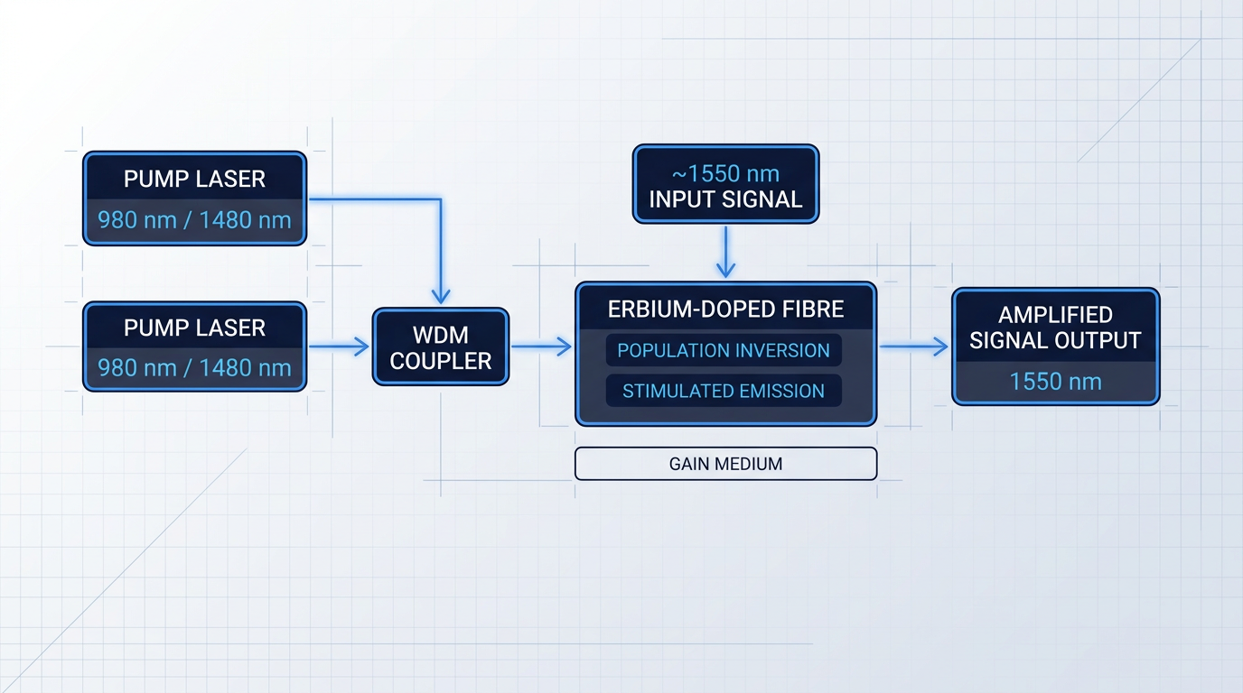
An EDFA is an optical amplifier whose gain medium is a length of optical fibre with erbium ions (Er³⁺) incorporated into the silica glass core. It operates in the 1550 nm C-band, the wavelength window that has become the standard for satellite free-space optical (FSO) communications.
How an EDFA Amplifies Light
Amplification begins with a pump laser diode — typically operating at 980 nm or 1480 nm — whose output is coupled into the erbium-doped fibre alongside the signal. The pump energy excites Er³⁺ ions from their ground state to a metastable excited state, establishing a population inversion in which more ions occupy the excited state than the ground state.
When an incoming signal photon at ~1550 nm encounters an excited Er³⁺ ion, it triggers stimulated emission: the ion releases a photon at the same wavelength, phase, and propagation direction as the signal photon, producing coherent gain.
Critically, this is all-optical gain — the signal remains in the optical domain throughout, with no electrical-to-optical conversion at any stage, which preserves signal fidelity and enables the high data rates demanded by modern lasercom terminals.
Two Roles in a Lasercom Terminal
In a satellite optical communications terminal, EDFAs serve in two distinct functional configurations, each with a different performance priority.
- Booster Amplifier: Sits on the transmit side. Amplifies a modulated seed laser to the high output power needed to overcome free-space path loss. Output power is the dominant design priority.
- Pre-Amplifier: Sits on the receive side. Amplifies a very weak incoming signal before photodetection. Minimising noise figure is the dominant design priority to preserve signal-to-noise ratio.
These two roles are not interchangeable: a booster optimised for maximum output power will carry a higher noise figure than is acceptable in a pre-amplifier, while a low-noise pre-amplifier design is not engineered to deliver the output levels a transmit chain requires.
The 1550 nm wavelength is not an arbitrary choice for either role. Three practical advantages converge at this band: it falls within an atmospheric transmission window relevant to ground-to-space and downlink paths; it sits within standard eye-safe laser classifications, which simplifies ground terminal operation and regulatory compliance; and it benefits from a vast, mature component ecosystem — pump lasers, connectors, detectors, modulators — developed over decades of terrestrial telecom infrastructure and available at high reliability and volume.
From Terrestrial to Space: A Different Discipline
A ground-based EDFA is designed to compensate fibre loss in a controlled environment: stable ambient temperature, convective cooling, no radiation exposure, and vibration limited to ordinary handling.
A satellite EDFA must survive and perform reliably across a qualitatively different set of conditions: launch loads (vibration, acoustic shock); hard vacuum (no convective cooling path, outgassing risks for polymers and adhesives); extreme thermal cycling across hundreds of orbits per year in LEO; and accumulated ionising radiation over a multi-year mission lifetime.
A satellite EDFA is not a terrestrial EDFA with added shielding. The space environment imposes demands — radiation, vacuum, thermal cycling, launch loads — that require a distinct engineering discipline from the ground up.
Each of these environmental factors places unique demands on the performance parameters that define an EDFA's usefulness in a space optical link: gain, output power, noise figure, wall-plug efficiency, and radiation tolerance are all shaped by the space environment in ways that ground-based qualification processes are simply not designed to address.
With that foundation in place, the next step is to understand how free-space path loss drives the specific performance requirements placed on both the booster and pre-amplifier — and why those requirements push satellite EDFA design to its limits.
The Role of EDFAs in Satellite Free-Space Optical Links
Optical power in free space does not simply fade with distance — it falls with the square of range, and satellite link distances compress that physics into a brutal engineering constraint.
For LEO satellite-to-satellite crosslinks spanning thousands of kilometres, closing the link can require an optical power budget on the order of ~70 dB to compensate for diffraction-limited beam divergence — a figure that makes watt-class transmitted power not a luxury, but the baseline condition for a viable link.
Two Roles in a Lasercom Terminal
A lasercom terminal places an EDFA at two distinct points in the signal chain, each with its own critical performance axis.
- Booster (transmit side): Takes a milliwatt-level modulated seed signal and amplifies it to watt-class output power, providing the transmitted energy needed to survive the full link distance.
- Pre-amplifier (receive side): Amplifies the extremely weak received signal before the photodetector. Noise figure is the critical parameter here, as any added noise directly sets the receiver sensitivity floor.
The booster determines how much optical power arrives at the far end; the pre-amplifier determines how weak a signal can still be usefully detected — together they define the ends of the link budget.
EDFAs excel in both roles because they combine high gain, high saturated output power, and a low noise figure that approaches the fundamental limit for phase-insensitive amplification — all within the 1550 nm C-band where the broader component ecosystem already operates.
Critically, EDFAs are agnostic to modulation format: whether the terminal uses coherent DPSK, dual-polarisation QPSK, or direct-detection OOK, the amplifier imposes no format-specific penalty, which matters as satellite FSO systems increasingly adopt high-spectral-efficiency coherent waveforms.
NASA's TBIRD (TeraByte InfraRed Delivery) programme provides the clearest on-orbit proof of what these parameters demand in practice: the TBIRD space terminal used an EDFA to wavelength-division-multiplex two 100 Gbps channels and boost the combined signal to 800 mW output power, delivering a 200 Gbps downlink from LEO to a ground station in California.
That entire transmit chain — EDFA included — was packaged into a 3U payload volume hosted aboard a 6U CubeSat, a platform weighing less than 12 kg, demonstrating that watt-class optical amplification is achievable even under severe size and mass constraints.
The TBIRD mission closed a 200 Gbps LEO downlink by boosting two WDM channels to 800 mW with an EDFA in a 3U payload — a direct, on-orbit demonstration that the output power specification of a satellite EDFA is not a design preference but a link budget requirement.
Semiconductor optical amplifiers (SOAs) offer a compelling alternative on paper: their photonic integrated circuit form factor is smaller, and they convert electrical power directly to amplified optical output without the two-stage architecture an EDFA requires.
In practice, however, SOAs suffer from fast gain dynamics that produce cross-gain saturation and four-wave mixing when operating near saturation with multi-channel WDM signals or coherent modulation formats — effects that are not minor inconveniences but disqualifying impairments for the high-data-rate, multi-channel applications that satellite FSO links increasingly demand.
The broader shift toward satellite optical communications is itself the backdrop that makes amplifier selection consequential: optical links offer wider bandwidth, higher achievable data rates, no RF spectrum licensing requirements, and narrower beams that reduce interference and improve link security — advantages that have driven rapid proliferation of lasercom payloads across LEO constellations.
With the link-budget rationale for EDFA selection established, the next question is what the space environment demands of an amplifier that must sustain this level of performance across a multi-year mission — a challenge that separates space-qualified EDFA design from its terrestrial counterpart in ways that go far beyond packaging.
The Space Environment as an Engineering Constraint
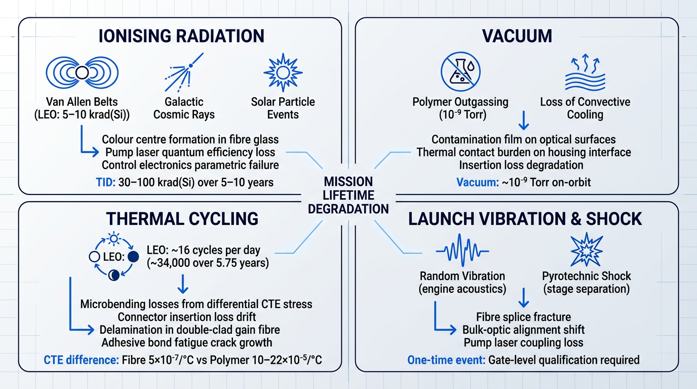
Designing an EDFA for terrestrial optical networks is a well-understood engineering problem. Designing one that must perform to specification after years in orbit is a fundamentally different challenge — not because any single stressor is insurmountable, but because the space environment imposes four distinct categories of degradation simultaneously, and they interact in ways that ground-based qualification cannot fully anticipate.
Ionising Radiation: Accumulated Damage Over Mission Life
The orbital radiation environment has three primary particle sources: protons and electrons trapped in the Van Allen belts, galactic cosmic rays (GCR) originating outside the solar system, and solar particle events (SPE) generated by solar flares and coronal mass ejections.
The cumulative radiation exposure an EDFA must survive is quantified as Total Ionising Dose (TID), measured in krad(Si). NASA photonics qualification data indicates that typical space-flight background radiation totals 30–100 krad(Si) over a 5–10 year mission, with LEO orbits accumulating roughly 5–10 krad(Si) (dominated by South Atlantic Anomaly passes), GEO orbits reaching approximately 50 krad(Si) from cosmic rays and trapped electrons, and MEO orbits — which transit the Van Allen belts directly — accumulating 10–100 krad(Si) depending on altitude and shielding.
For an EDFA, accumulated TID creates degradation pathways across multiple component classes: colour centres form in the glass fibre matrix, increasing optical attenuation; pump laser diodes suffer displacement damage that degrades quantum efficiency and threshold current; and control electronics accumulate parametric failures in transistors and memory devices.
TID is a mission-design input, not a fixed number — the orbit, mission duration, and shielding architecture together determine what the EDFA must survive, and that determination must be made at the system level before component selection begins.
Vacuum: Outgassing and the Loss of Convective Cooling
The space vacuum environment creates two distinct engineering problems for an EDFA, and conflating them leads to incomplete design responses.
The first is outgassing: polymer materials used in fibre coatings, buffer layers, adhesives, and connector components release volatile compounds when exposed to high vacuum (on-orbit vacuum is approximately 10⁻⁹ Torr). These volatiles can redeposit on optical surfaces — lenses, fibre endfaces, connector ferrules — forming thin contamination films that increase insertion loss and degrade link performance over time. This is fundamentally a materials-selection constraint: every non-metallic material in the EDFA assembly must be evaluated for vacuum outgassing compliance before flight.
The second effect is the removal of convective cooling. On the ground, heat generated by the EDFA's pump laser diodes and drive electronics is partially dissipated by convective airflow. In vacuum, convection does not exist — only conduction and radiation remain as heat transfer mechanisms. This shifts the entire thermal management burden to the mechanical interface between the EDFA housing and the spacecraft structure, making that thermal contact path a first-class design concern rather than an afterthought.
Thermal Cycling: Cumulative Mechanical Fatigue
A LEO satellite completes an orbital period of roughly 90 minutes, cycling between sunlit and eclipse conditions approximately 16 times per day. Over a multi-year mission, this translates to thousands of thermal cycles — the LDEF experiment, which flew for 5.75 years, experienced approximately 34,000 thermal cycles.
The engineering problem is differential thermal expansion. An EDFA contains dissimilar materials — fused silica fibre, polymer coatings and buffer layers, metal packaging, and adhesive bonds — each with a different coefficient of thermal expansion (CTE). The fused silica fibre core has a CTE of approximately 5×10⁻⁷/°C, while polymer jacket materials typically expand at 10–22×10⁻⁵/°C, a difference of nearly two orders of magnitude.
At every thermal interface, each cycle imposes mechanical stress. Over thousands of cycles, this manifests as microbending losses in the fibre (where lateral stress deforms the fibre core, coupling guided light into cladding modes and increasing attenuation), connector insertion loss drift, delamination risk in double-clad gain fibre structures, and fatigue crack growth at adhesive bonds.
Critically, thermal cycling is a cumulative fatigue problem, not a single-event failure mode. Each cycle deposits a small increment of mechanical damage; no individual cycle is catastrophic, but the total damage over a 10-year GEO mission can be decisive for components that were not designed with this accumulation in mind.
Launch Vibration and Shock: One-Time but Severe
Before an EDFA ever reaches orbit, it must survive the launch environment. Random vibration from rocket engine acoustics and structural resonance, and pyrotechnic shock from explosive separation events — stage separation, payload fairing jettison — impose mechanical loads that ground-based packaging is not designed to withstand.
The most vulnerable EDFA sub-components are those with tight mechanical tolerances or bonded interfaces: fibre splices (where the fibre is fused or mechanically joined to other components), bulk-optic alignments (where isolators, wavelength-division multiplexers, or couplers are bonded in free space with micron-level alignment requirements), and pump laser packaging (where the laser diode is coupled to the fibre pigtail through a lens system with submicron alignment tolerances).
Unlike radiation or thermal cycling, launch loads are a one-time event — but they are severe enough to cause immediate, catastrophic failure if packaging is inadequate. This makes vibration and shock testing a gate-level qualification requirement: a satellite EDFA that has not passed random vibration and shock testing to launch vehicle levels is not flight-qualified, regardless of its optical performance.
Why Environments Cannot Be Evaluated in Isolation
The four stressors described above are not independent. They interact and compound in ways that make sequential single-environment ground testing an insufficient predictor of on-orbit performance.
The most consequential interaction involves radiation and temperature. Thermal annealing is the natural process by which radiation-induced colour centres in optical fibre partially recover at room temperature — defects formed by ionising radiation are thermally unstable and gradually dissipate when the fibre is warm. But when a LEO satellite enters eclipse, fibre temperatures can drop well below room temperature. At cold temperatures, annealing is suppressed, meaning radiation damage accumulates faster than ground tests conducted at room temperature would predict.
NASA GSFC fibre optic radiation testing has confirmed this effect directly: optical fibre tested under irradiation at −125°C showed significantly higher radiation-induced attenuation than the same fibre tested at room temperature under identical dose conditions, because the colour centre recovery mechanism was thermally inhibited.
Vacuum and thermal cycling also interact. Vacuum lowers the partial pressure threshold at which volatile compounds are released from polymer materials, accelerating outgassing relative to atmospheric testing. Additionally, thermal cycling in vacuum removes the damping effect of atmospheric pressure on micro-crack propagation in adhesive bond lines, potentially increasing the mechanical fatigue rate at those interfaces compared to cycling in air.
A ground test that applies radiation at room temperature, then thermal cycling at atmospheric pressure, then vacuum separately will not replicate the synergistic degradation that occurs when all stressors act simultaneously in orbit. The LDEF experiment — which flew fibre optic samples for 5.75 years — demonstrated that no laboratory work had previously attempted to realistically simulate the combined environment of radiation, temperature, and vacuum found on an orbital spacecraft.
Mission Lifetime as the Compounding Factor
A 10-year GEO mission does not present these stressors sequentially — it applies them simultaneously and continuously from the moment of launch. The engineering challenge is not surviving any one stressor at a point in time; it is maintaining EDFA gain, noise figure, and output power within specification across all stressors over the full mission duration.
The professional engineering response to this inherent uncertainty is twofold: conservative design margins that budget for beginning-of-life to end-of-life performance degradation across all stressor categories, and in-orbit monitoring capability — telemetry for gain drift, pump laser drive current, and operating temperature — that allows ground operators to detect and respond to performance changes as they develop.
Of the four stressors, ionising radiation and its effect on the erbium-doped gain fibre is the most consequential for EDFA gain and noise figure. The next section examines the specific mechanisms by which radiation damages the fibre — colour centre formation, its wavelength dependence, and the factors that determine whether a given fibre will maintain acceptable performance over a mission lifetime.
Radiation-Induced Attenuation: Mechanisms and Consequences
Most engineers working with erbium-doped fibre in space applications know that radiation increases attenuation. Fewer appreciate that the primary driver of that sensitivity has almost nothing to do with erbium — and that the degradation mechanism compounds across multiple performance parameters simultaneously, in a causal chain that runs all the way from atomic-scale defects to link margin erosion.
Colour Centres: The Root Physical Mechanism
When ionising radiation passes through the silica glass matrix of an erbium-doped fibre, it deposits energy that displaces atoms and ionises the glass network, creating localised structural defects known as colour centres (also called point defects or radiation-induced defects).
A colour centre is a lattice irregularity — a dangling bond, an oxygen vacancy, a trapped electron or hole — that creates localised electronic states within the bandgap of the glass, states that can absorb photons across a broad wavelength range.
The result is radiation-induced attenuation (RIA): an increase in the fibre's linear absorption that is both wavelength-dependent and time-dependent, and that accumulates with total ionising dose over the mission lifetime.
Dopant Dominance: Aluminium, Not Erbium
The counterintuitive finding that consistently emerges from the RIA literature is that the rare-earth dopant responsible for optical gain — erbium itself — is not the primary determinant of radiation sensitivity.
Instead, it is the aluminium co-dopant (Al₂O₃) content that dominates the radiation response. Aluminium is incorporated into erbium-doped fibre to broaden and flatten the gain spectrum and to improve erbium solubility, preventing ion clustering that would quench the luminescence.
The radiation penalty for this benefit is severe. NASA NEPP data comparing two Yb-doped fibres with similar rare-earth concentrations but different aluminium contents — 1.0 mol% versus 4.2 mol% Al₂O₃ — showed RIA of 1 dB/m versus 12 dB/m at the same 14 krad total dose: a factor of twelve difference driven entirely by aluminium content.
A separate study cited in NASA GSFC documentation confirmed that simply altering aluminium content can increase radiation-induced darkening by an order of magnitude, while large variations in erbium concentration produce comparatively little change in RIA.
The mechanism is the aluminium oxygen hole centre (Al-OHC): when four-coordinated aluminium substitutes for silicon in the silica network, a hole trapped on a bridging oxygen adjacent to the aluminium site creates a defect centre with absorption bands that extend into the near-infrared, directly overlapping the pump and signal wavelengths used in EDFAs.
Doubling the Al2O3 co-dopant content in erbium-doped fibre can increase RIA by an order of magnitude, while large changes in erbium concentration produce comparatively little effect. Fibre selection — specifically, minimising aluminium content — is therefore the primary radiation-hardening lever at the material level.
Wavelength Dependence: The Pump Penalty
RIA is not spectrally uniform, and the asymmetry is particularly damaging for EDFA operation: attenuation at the 980 nm pump wavelength is substantially higher than at the 1550 nm signal wavelength.
| Fibre | Er Content | Al (mol%) | Ge (mol%) | RIA Sensitivity at 980 nm (dB/m·krad) | RIA Sensitivity at 1300 nm (dB/m·krad) | RIA Sensitivity at 1550 nm (dB/m·krad) |
|---|---|---|---|---|---|---|
| HE980 | 4.5×10²⁴ /m³ | 12 | 20 | 0.013 | 0.0041 | 0.0025 |
| HG980 | 1.6×10²⁵ /m³ | 10 | 23 | 0.012 | 0.0038 | No data |
Quantitative comparison of RIA sensitivity at pump and signal wavelengths for two commercial Er-doped fibres, showing the order-of-magnitude wavelength dependence from NASA GSFC data.
The data confirm what NASA GSFC extrapolation modelling reinforces: at 200 krad total dose under low dose-rate conditions representative of orbital exposure, the HE980 fibre accumulates approximately 1.50 dB/m of RIA at 980 nm versus only 0.10 dB/m at 1550 nm — a fifteen-fold difference across the same fibre at the same dose.
This asymmetry is critical for population inversion. Pump photons at 980 nm are absorbed preferentially by colour centres rather than by Er³⁺ ions, reducing the fraction of pump power available to excite the gain transition. Even when signal-wavelength attenuation remains modest, pump absorption can be sufficiently impaired to compress gain significantly.
Research on 1480 nm pumping indicates that RIA characteristics at that wavelength differ from those at 980 nm, with photobleaching behaviour also diverging: one study found that photobleaching at 980 nm pump wavelengths produced measurable recovery of radiation-induced absorption, whereas no equivalent photobleaching effect was observed with 1480 nm pumping.
Dose-Rate Effects and the Extrapolation Challenge
Laboratory radiation testing — using Co-60 gamma sources or proton accelerators — delivers dose rates orders of magnitude higher than what a satellite experiences in orbit. As noted in NASA GSFC documentation, most space flight environments produce gamma exposure rates of less than 1 rad(Si)/min, and more typically below 0.01 rad(Si)/min. Typical mission parameters include 30–100 krad(Si) accumulated over five to ten years.
At high laboratory dose rates, radiation-induced defects accumulate faster than the glass matrix can thermally anneal them, so RIA builds up more rapidly than it would at orbital rates. Reducing the dose rate by two to three orders of magnitude can reduce RIA by approximately one order of magnitude for the same total dose — a relationship documented across multiple NASA GSFC fibre studies.
To bridge this gap, NASA researchers apply dose-rate extrapolation models — most commonly power-law expressions of the form A(D) = C·φⁿ·D^f, where A(D) is the induced attenuation, φ is the dose rate, D is the total dose, and the constants are determined from two or more test conditions. This approach was formalised by Friebele, Gingerich, and Griscom at NRL and has been applied extensively in NASA GSFC fibre qualification work.
The inherent limitation of this approach must be acknowledged honestly: ground testing cannot perfectly replicate orbital conditions, and the uncertainty in extrapolated values grows with the magnitude of the dose-rate gap being bridged. The NASA ETW 2025 fibre update from the Goddard Photonics Group explicitly flags that fibres are often dark during their highest radiation exposure in flight, and that post-irradiation measurements taken without in-situ monitoring will underestimate peak RIA because fibres anneal rapidly after irradiation ceases.
This extrapolation uncertainty is a principal reason why conservative design margins — and, as §7 will discuss, in-situ monitoring during qualification testing — are non-negotiable for satellite EDFA programmes.
Temperature Dependence and Saturation Behaviour
Thermal annealing — the spontaneous recovery of radiation-induced colour centres driven by thermal energy — partially offsets RIA during and after irradiation. At higher temperatures, trapped charges are released more readily, limiting the net accumulation of colour centres. At lower temperatures, this annealing is suppressed.
NASA CABASS radiation documentation notes that the radiation-induced loss sensitivity can vary by a factor of 25 between temperature extremes, with the worst case at the low end of the operating range — a range that is directly relevant to satellite EDFAs, which can experience cold temperatures during eclipse.
Erbium-doped and Er/Yb fibres also exhibit saturation behaviour: as dose accumulates at a constant dose rate, the rate of new colour centre creation eventually reaches equilibrium with the annealing rate, and RIA plateaus at a steady-state value rather than increasing without limit.
This saturation level is not a universal constant — it is a function of temperature, dose rate, and fibre composition, and must be characterised for the specific fibre under the specific operating conditions. A fibre that saturates at an acceptable attenuation level under one set of conditions may continue increasing under a different dose rate or at a lower temperature.
Photobleaching: A Third Recovery Mechanism
In an actively pumped EDFA, the pump light itself drives partial recovery of radiation-induced absorption — a phenomenon called photobleaching (or photo-annealing under pump illumination). This is physically distinct from thermal annealing, which is temperature-driven and occurs in the dark.
Three recovery mechanisms must therefore be distinguished and modelled separately: (1) photobleaching during active operation, driven by pump photon interactions with colour centre populations; (2) thermal annealing, driven by temperature and occurring whether the amplifier is pumped or not; and (3) post-irradiation dark recovery, which is the spontaneous partial recovery observed after irradiation ceases with no optical power present.
Quantitative data from Ladaci (2017) and Mady et al. (IEEE TNS) on an erbium-doped fibre irradiated to 330 krad show that RIA at the pump wavelength decreased from approximately 18 dB/m in the unpumped condition to approximately 6.8 dB/m at 180 mW pump power — a reduction of roughly 62%. At the signal wavelength, the corresponding reduction was approximately 50%, from around 5 dB/m to 2.5 dB/m.
The magnitude of photobleaching depends on pump power and wavelength. Critically, photobleaching is non-uniform along the fibre length: pump power is highest at the amplifier input and diminishes as it is absorbed, so colour centre populations — and their recovery under photobleaching — vary spatially along the gain fibre in ways that ground-based short-sample measurements may not fully capture.
A lifetime model that omits photobleaching will overestimate in-service RIA and produce unnecessarily pessimistic link margin predictions. Conversely, a model that assumes photobleaching at its maximum measured value without characterising its pump-power dependence will be optimistic. Both errors have operational consequences.
From Colour Centres to Link Margin: The Consequence Chain
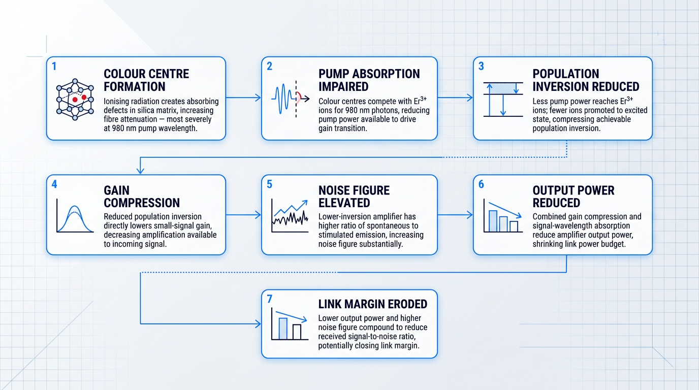
The reason radiation hardness must be addressed at design time — not treated as a qualification formality — is that RIA does not degrade a single performance parameter in isolation. It initiates a compounding chain of effects that simultaneously erodes gain, noise figure, and output power.
- Colour centre formation: Ionising radiation creates absorbing defects in the silica matrix, increasing fibre attenuation across the spectrum — most severely at the pump wavelength.
- Pump absorption impaired: Colour centres compete with Er³⁺ ions for 980 nm photons, reducing the fraction of pump power available to drive the gain transition.
- Population inversion reduced: With less pump power reaching the Er³⁺ ions, fewer ions are promoted to the excited state, compressing the achievable population inversion.
- Gain compression: Reduced population inversion directly lowers the small-signal gain of the amplifier, decreasing the amplification available to the incoming optical signal.
- Noise figure elevated: A lower-inversion amplifier has a higher ratio of spontaneous emission to stimulated emission, increasing the noise figure — sometimes substantially.
- Output power reduced: Combined gain compression and direct signal-wavelength absorption reduce the amplifier's output power, shrinking the power budget available to the link.
- Link margin eroded: Lower output power and higher noise figure compound to reduce the received signal-to-noise ratio, potentially closing the link margin over mission lifetime.
Experimental confirmation of this chain is available in the literature: one study on an electron-irradiated EDFA (10 kGy total dose) reported output power dropping from +10 dBm to −60 dBm for the same pump level, with the noise figure simultaneously deteriorating — both parameters recovering only partially over a two-week period.
The compounding nature of this chain is what makes radiation hardness a design-time commitment. Each step amplifies the impact of the previous one: a modest increase in pump-wavelength attenuation translates to a disproportionate reduction in population inversion, which then drives gain compression and noise figure degradation simultaneously. There is no post-hoc fix once the fibre is on orbit.
With the physical mechanisms and their consequences now established, the engineering question becomes: how do fibre selection, amplifier architecture, and qualification testing respond to these constraints? That is the subject of the next section.
Radiation Hardening Strategies and Space Qualification Testing
Understanding why radiation degrades a satellite EDFA is necessary but not sufficient. The engineering question that follows is more demanding: given the mechanisms, what design commitments does a responsible team make before a component ever enters a test facility, and what does the qualification programme need to prove?
Radiation Hardening: Design-Time Commitments
Because aluminium content in the glass matrix drives colour centre formation under ionising radiation, fibre composition is the single most impactful design-time decision available to a space EDFA engineer.
Specifying low-aluminium or pure-silica-core erbium-doped and erbium/ytterbium co-doped fibres can reduce radiation-induced attenuation by an order of magnitude compared with conventional alumino-silicate formulations. Suppliers including Exail and Coherent Nufern offer space-grade fibres specifically characterised for radiation environments, with published datasheets intended to support mission dose budget analysis.
A second materials-level lever is cerium co-doping. Ce³⁺ ions act as hole traps in the glass matrix, limiting the formation of radiation-induced defect centres and stabilising the Er³⁺ lasing properties under accumulated dose.
Published research in SPIE conference proceedings on radiation effects in space fibre optics has demonstrated that cerium co-doped fibres show reduced radiation-induced gain degradation and suppress phosphorus-related defect centres that appear in non-Ce-doped equivalents. This is an active area of materials research with documented, measurable benefit.
- Low-Al fibre selection: Pure-silica-core or low-aluminium erbium and Er/Yb fibres minimise colour centre formation, delivering order-of-magnitude RIA reduction versus standard alumino-silicate formulations.
- Cerium co-doping: Ce³⁺ ions trap holes in the glass matrix, suppressing defect centre formation and stabilising gain under accumulated ionising dose.
- Local shielding: Tungsten or tantalum enclosures around the gain fibre coil and pump reduce total ionising dose at the most radiation-sensitive elements, traded against spacecraft mass.
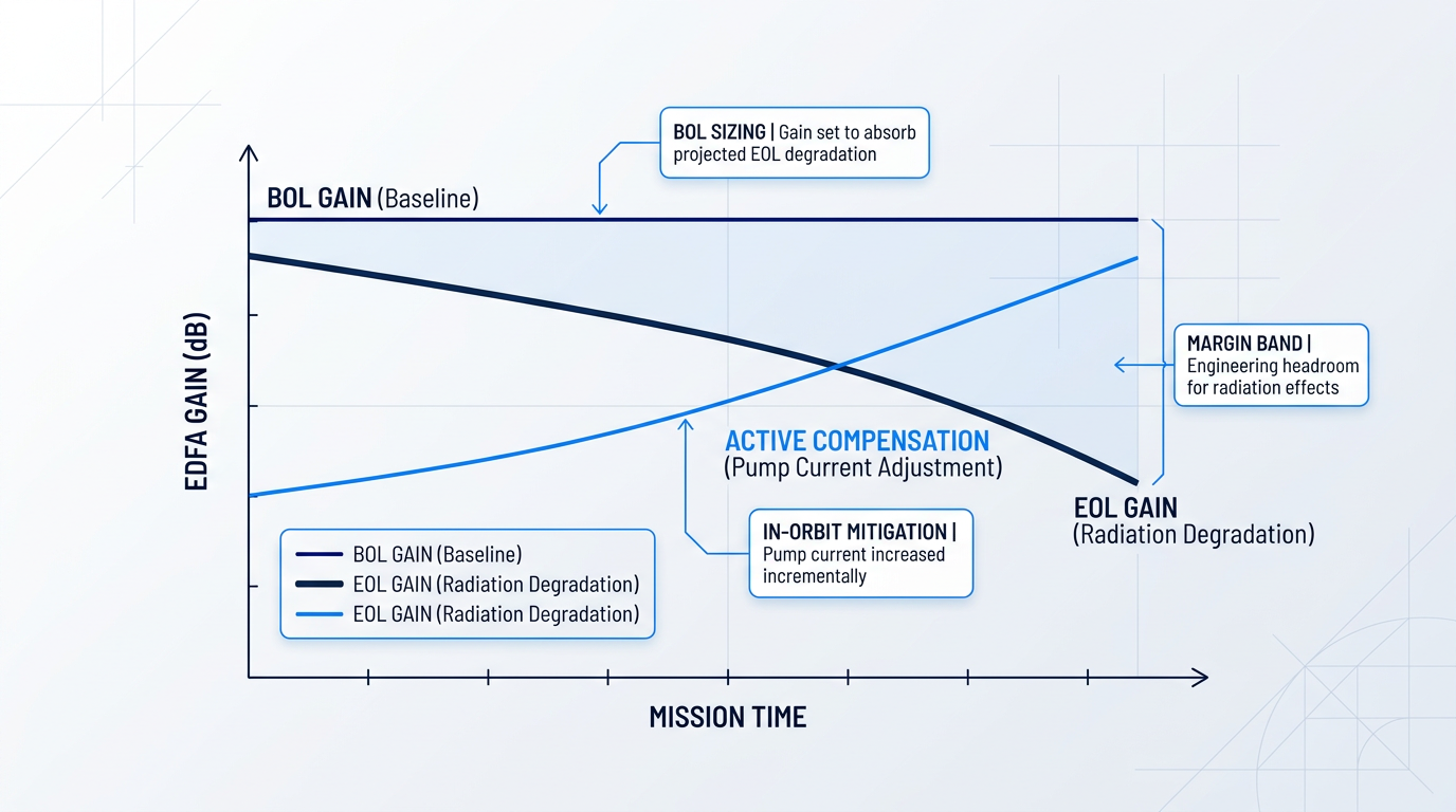
- BOL-to-EOL gain margin: Gain is sized at beginning-of-life to absorb projected end-of-life degradation, with active pump current compensation providing in-orbit headroom as dose accumulates.
Local shielding using high-density materials such as tungsten or tantalum around the gain fibre coil and pump diode assembly reduces the total ionising dose reaching the most sensitive elements.
Shielding effectiveness scales with areal density, but spacecraft mass budgets are finite. The practical implication is that shielding complements radiation-hardened fibre selection; it cannot substitute for it.
Sizing the BOL-to-EOL gain margin requires orbit-specific dose modelling that accounts for mission duration, shielding configuration, and the RIA characteristics of the chosen fibre.
Active pump current compensation — incrementally increasing drive current to offset radiation-induced gain compression as the mission progresses — is a practical in-orbit mitigation strategy. The pump laser must carry sufficient current headroom at end-of-life, and the control architecture must support closed-loop pump adjustment; that control capability is addressed in detail later in this guide.
The Qualification Test Programme as Diagnostic Evidence
A qualification test programme is only as valuable as the failure modes it is designed to surface. For a space EDFA, each environmental test probes a specific set of design vulnerabilities — and the results constitute evidence of engineering understanding, not confirmation that a standard has been satisfied.
Thermal Vacuum Cycling
Thermal vacuum cycling exposes failure modes that ground-level thermal testing cannot reach. In double-clad fibre designs, differential thermal expansion between glass and polymer coatings can cause fibre delamination across repeated cycles.
Adhesives can outgas onto optical surfaces in vacuum, progressively degrading coupling efficiency. Connector insertion loss also drifts across temperature cycles in ways that are not apparent at ambient pressure.
Pump laser wavelength shifts with temperature, directly affecting pump absorption efficiency in the gain fibre — a performance degradation that compounds with other thermal effects under vacuum conditions.
The critical discipline is that TVAC testing must include in-situ optical performance monitoring with the EDFA powered and lasing throughout the full thermal cycle. Several degradation modes manifest only under active operation in vacuum and are entirely invisible in passive, unpowered testing.
Vibration and Shock Testing
Random vibration testing at launch-representative levels, as defined in standards such as NASA-STD-7002B and ECSS-E-10-03A, is designed to expose failures in fibre splices, bulk-optic coupling alignments, and pump laser packaging — the mechanical joints that accumulate fatigue under broadband excitation.
Pyrotechnic shock at stage separation delivers a high-frequency, high-amplitude impulse that is particularly stressful for connectorised optical interfaces. Fusion-spliced, all-fibre designs carry an inherent robustness advantage: there are no bulk-optic coupling points to shift under the shock load.
Bulk-optic coupling points require careful mechanical packaging validation to survive pyrotechnic events. The vibration and shock sequence reveals which design choices were adequate and which were not — its value is diagnostic, not merely confirmatory.
Radiation Testing: The Dose-Rate Challenge
Space dose rates are orders of magnitude lower than what Co-60 gamma sources or proton beam facilities can deliver in practical test durations. This gap is the central methodological challenge of radiation qualification for space fibre optics.
Accelerated testing at high dose rates suppresses the thermal annealing that would occur at lower, space-representative rates, causing the test to systematically overestimate RIA. Dose-rate effects must therefore be explicitly accounted for in test design, not treated as a conservative margin.
Optical fibres anneal rapidly once irradiation ceases, so ex-situ measurements taken after the beam is switched off systematically underestimate the true in-orbit RIA. In-situ optical monitoring during irradiation — and during TVAC cycling — is the only way to observe the degradation the space environment will actually impose.
Experienced qualification teams design radiation test protocols with continuous in-situ optical monitoring and apply dose-rate correction models to translate accelerated test results to space-representative conditions. This methodology is documented in NASA technical literature on space fibre optic components and represents the professional standard for satellite EDFA characterisation.
Materials Qualification Philosophy
Vacuum-exposed polymer materials must pass outgassing screening before acceptance for space use. The widely applied standard is ASTM-E595, which sets limits on total mass loss and collected volatile condensable material — thresholds that gate whether a material is suitable for vacuum environments.
Telcordia certification standards provide a useful commercial reliability baseline for optical components, but they do not cover vacuum or radiation environments. Space qualification requires upscreening beyond that baseline to address the conditions a satellite EDFA will actually encounter.
The professional standard for mission-critical components is lot-based qualification: each production lot is screened independently rather than relying on a one-time type qualification. The underlying philosophy is consistent throughout — the qualification programme exists to catch the failure modes the space environment will expose, not to satisfy a checklist.
With radiation hardening strategies and qualification evidence established, the next consideration is how these design choices interact with the output power and efficiency specifications that satellite link budgets demand — the subject of the following section.
See Our Custom EDFAs for Space Optical Links
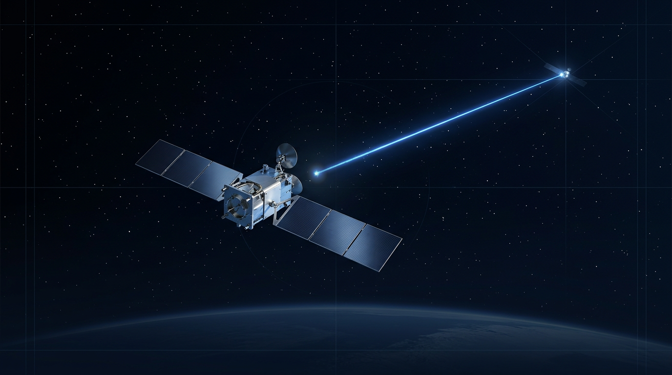
Our EDF-UL-10 is a 10 W EDFA for optical ground-station uplinks and beacons, serving links to satellites in any orbit. Each unit is configurable to your ground-station requirements.
Output Power, Efficiency, and Noise Figure for Link Budgets
In terrestrial optical networks, an EDFA's output power and noise figure are specified largely in isolation from the power supply or cooling system — those are infrastructure problems, solved by plugging into a rack and bolting on a heat exchanger. On a spacecraft, that separation disappears entirely. The amplifier's optical performance, the satellite's power generation budget, and its thermal rejection capacity are a single coupled engineering problem, and every specification number must be understood in that context.
Output power is not a product-catalogue choice — it is derived from link budget analysis, working backwards from the free-space path loss the link must overcome.
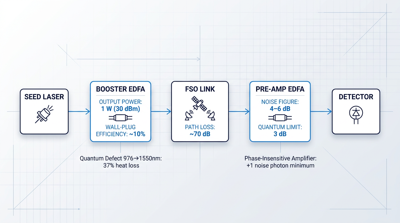
Free-space path loss grows with the square of link distance and shrinks with aperture area, so the EDFA's role as a booster amplifier is to raise the modulated seed laser to whatever power level closes the link at the required range and bit-error rate. For LEO inter-satellite crosslinks, SPIE proceedings on satellite laser communication identify approximately 1 W (30 dBm) as a representative output power benchmark, sufficient to support a ~70 dB optical power budget across distances exceeding 5,000 km when combined with adequate receive aperture gain.
The upper frontier of output power requirements is moving fast. ESA's EPOS programme (Extremely Powerful Optical Sources) is targeting a 100 W C-band spaceborne amplifier as an enabling component for Tbit/s inter-satellite links — a two-orders-of-magnitude step beyond current LEO ISL practice that illustrates how future high-capacity links will redefine what the EDFA must deliver.
The link budget sets the output power requirement; the spacecraft power budget then sets the engineering ceiling on how that requirement can be met. This is where wall-plug efficiency becomes the parameter that most tightly couples the EDFA to the rest of the spacecraft.
At 1550 nm, electrical-to-optical conversion efficiency for Er/Yb-doped fiber amplifiers using standard 976 nm pump diodes is typically less than 20%, and commonly around 10% in practical hardware — a figure confirmed by JPL IPN Progress Report 42-189 and consistent with ESA programme data showing an 11% wall-plug efficiency for a 10 W EOL space-qualified Er/Yb amplifier.
The root cause is the quantum defect: the energy difference between the 976 nm pump photon and the 1550 nm signal photon means that approximately 37% of the absorbed pump energy is lost as heat through phonon relaxation, before any other loss mechanism is considered. According to JPL IPN Progress Report 42-189, the quantum defect for 976 nm pumping gives a Stokes efficiency of only 0.63 — a fundamental physical ceiling, not an engineering shortfall that can be designed away.
The practical consequence is stark: the majority of the electrical power consumed by the amplifier becomes waste heat that must be removed from the spacecraft.
Wall-plug efficiency is simultaneously an optical performance parameter and a spacecraft power and thermal engineering constraint — making it the single specification that most tightly integrates the EDFA into the rest of the satellite's system design.
Two architectural approaches found in space-qualified satellite EDFA designs address the efficiency ceiling directly. Double-clad Er/Yb fibre guides multimode pump light in a large inner cladding while confining the signal to a single-mode core, dramatically improving pump coupling efficiency and enabling the watt-class output powers that LEO and GEO links demand. A dual-clad double-pass design demonstrated at SPIE Volume 11180 achieved around 7 W output with optical-to-optical conversion efficiency exceeding 32%, illustrating the practical gain this geometry provides.
Double-pass configurations using a Faraday mirror reflect the signal back through the gain fibre for a second amplification pass, achieving high gain with fewer active components and producing a polarisation-maintaining output without a dedicated PM gain stage. Critically, the geometry also limits amplified spontaneous emission accumulation on the first pass — a noise management benefit that connects directly to the receive-chain performance discussed below.
On the receive side of the link, the critical parameter shifts from output power to noise figure. For a pre-amplifier EDFA, noise figure determines the minimum signal power that must arrive at the receiver to achieve a target bit-error rate — lower noise figure means the link can close with a weaker received signal, which directly translates to longer range or a smaller transmit aperture.
Well-designed EDFAs achieve 4–6 dB noise figure in practice, a range confirmed across IEEE and SPIE technical literature for high-quality amplifiers operating in the C-band. The hard physical floor is 3 dB — the quantum noise limit for any phase-insensitive optical amplifier, arising from the fundamental requirement that such an amplifier must add at least one noise photon per signal mode. This is not a design target that can be surpassed through engineering refinement; it is a consequence of quantum mechanics.
The 1–3 dB gap between the quantum limit and real hardware performance reflects practical losses: incomplete population inversion, residual absorption, and component insertion losses. For a satellite systems engineer evaluating hardware, the 4–6 dB range is the meaningful benchmark: an amplifier at 4 dB is close to the physical limit; one at 6 dB has measurable margin to recover.
Amplified spontaneous emission (ASE) is the noise mechanism that sets the noise figure floor. Erbium ions in the excited state emit photons spontaneously across the gain bandwidth; those photons are then amplified alongside the signal, degrading the optical signal-to-noise ratio and reducing receiver sensitivity. The standard mitigation is a narrow bandpass optical filter at the amplifier output, which rejects out-of-band ASE while passing the signal channel.
The double-pass architecture with a Faraday mirror provides a secondary benefit here: by limiting ASE build-up on the first pass through the gain fibre, it reduces the total ASE power that the output filter must reject. ASE that is filtered out still represents pump energy that was converted to unwanted photons rather than signal — connecting the noise management problem back to the thermal management challenge.
The thermal management consequences of imperfect wall-plug efficiency are concrete and significant. Consider a satellite EDFA delivering 10 W of optical output at 10% wall-plug efficiency: the unit consumes approximately 100 W of electrical power and dissipates roughly 90 W as heat — a figure consistent with ESA programme data for a 10 W EOL Er/Yb space amplifier. In vacuum, there is no convective cooling pathway; every joule of waste heat must be rejected by radiation from a finite surface area or conducted to the spacecraft's thermal bus.
This makes thermal interface design between the EDFA and the spacecraft structure a first-class engineering concern, not a packaging afterthought. The JPL DESCANSO monograph on deep-space optical communications notes that dedicated radiators are generally more efficient than relying on the spacecraft radiator for laser transmitter thermal management, and that the heat-generating laser should ideally be physically separated from heat-sensitive optical components — a separation that fibre-fed EDFA architectures facilitate naturally.
Temperature management is not only about keeping components within survival limits; it is about maintaining optical performance within specification. Pump laser diode emission wavelength shifts with temperature at approximately 0.3 nm/°C, as documented in JPL DESCANSO Chapter 5 — a drift that can move the pump wavelength off the erbium absorption peak and reduce gain efficiency. The erbium gain spectrum itself is also temperature-sensitive, shifting the peak gain wavelength and altering the gain flatness across the C-band. Thermal management, in this context, is as much about stabilising the amplifier's optical transfer function as it is about preventing component failure.
These efficiency and thermal challenges apply to every space EDFA, regardless of orbit or application. They become especially acute, however, when the entire amplifier must fit within the constrained volume and power envelope of a CubeSat or small satellite payload — the engineering context that the next section addresses directly.
Miniaturised EDFA Design for CubeSat Platforms
A 6U CubeSat weighs roughly 12 kg and generates perhaps 30–50 W from deployed solar panels. Asking that platform to host a high-throughput optical downlink — with an EDFA boosting WDM channels to hundreds of milliwatts of transmit power — sounds like a contradiction in terms. It is not, but resolving the contradiction requires engineering decisions that interact across every layer of the EDFA design simultaneously: packaging geometry, power operating point, pump laser architecture, thermal interface, and qualification testing.
Volume and Mass: The Starting Constraint
The CubeSat form factor — 1U defined as 10×10×10 cm — imposes dimensional limits that cascade through every component selection decision in the optical payload.
Commercial space-qualified EDFA modules designed for CubeSat applications demonstrate what is achievable within these constraints: NuPhoton's space-qualified EDFA (model EDFA-CW-C0-VRS-30-30-FCA) packages a 30 dBm output amplifier into a 120×80×20 mm footprint — a module that fits within roughly 2U of volume while consuming no more than 14 W at 50°C case temperature.
One packaging approach that trades volume directly against design flexibility is the 2-in-1 configuration, which combines a pre-amplifier and booster stage in a single housing.
The volume and mass savings from a 2-in-1 design are genuine — a single integrated housing eliminates inter-stage connectors, reduces fibre routing complexity, and lowers total component count — but the cost is equally real: the two amplifier stages share thermal and electrical resources and cannot be independently optimised or controlled for different operating conditions.
For a mission where the pre-amplifier and booster will always operate in a fixed gain regime, the 2-in-1 approach is defensible; for a mission requiring adaptive gain management across varying link distances or atmospheric conditions, the loss of independent stage control becomes a genuine operational constraint.
Power Budget: From Desirable to Non-Negotiable
As discussed in the context of output power and efficiency, wall-plug efficiency is a spacecraft power constraint — waste heat from an inefficient EDFA must be dissipated, and the electrical power consumed cannot be recovered.
On a CubeSat, that constraint becomes acute: a 3U platform operating in LEO may generate 10–20 W from body-mounted solar panels, with the optical payload competing against housekeeping, attitude control, and communications overhead for every watt.
This changes the design objective fundamentally — on a large satellite, the EDFA operating point is optimised for maximum output power within the thermal budget; on a CubeSat, the operating point is optimised primarily for electrical efficiency, accepting lower output power if necessary to stay within the power allocation.
Inefficiency that produces waste heat is doubly costly on a small platform: it consumes scarce electrical power and deposits thermal load into a structure with very limited dissipation capacity.
Pump Laser Selection: The Uncooled Trade-Off
The choice of pump laser diode architecture is one of the most consequential levers available to the CubeSat EDFA designer, because the pump is typically the largest single consumer of electrical power in the amplifier.
Conventional space-qualified EDFAs use thermoelectric cooler (TEC)-stabilised pump diodes, which hold the laser junction at a fixed temperature to maintain precise wavelength output — but the TEC itself consumes power, often comparable to the pump diode's optical output power in the worst case.
Eliminating the TEC — operating an uncooled pump diode — removes this parasitic load, but introduces wavelength drift with temperature: free-running 976/980 nm InGaAs pump diodes shift at approximately 0.02 nm/°C with junction temperature, meaning a 30°C operating range produces roughly 0.6 nm of wavelength excursion.
Whether this drift is acceptable depends on the gain fibre selection: the erbium absorption band around 980 nm has a full-width at half-maximum of approximately 16 nm for aluminium-co-doped silica fibre (and approximately 11 nm for germanium-co-doped silica), as established by Pedersen et al. (IEEE PTL, 1992).
Pedersen et al. demonstrated experimentally that a gain penalty of less than 0.5 dB is achievable over an 18 nm pump wavelength range for appropriately designed power amplifiers — meaning that uncooled operation is not simply a degraded version of TEC-stabilised operation, but an acceptable design point if the gain fibre numerical aperture and length are selected with pump wavelength tolerance in mind.
The correct framing is not that uncooled pump diodes are inferior — it is that they are acceptable under the right conditions: a broad-absorption gain fibre matched to accommodate drift, operating within a bounded thermal range set by the spacecraft thermal design.
FBG-stabilised uncooled pump modules, which use a fibre Bragg grating to lock the emission wavelength without a TEC, offer an intermediate option: wavelength stability to below 0.02 nm/°C while eliminating the TEC power draw, at the cost of additional component complexity in the pump pigtail.
Thermal Management: Conduction as the Primary Path
In the vacuum of orbit, convective cooling is unavailable — a constraint the earlier discussion of the space environment established — but the severity of this constraint scales with platform size.
On a large satellite, dedicated radiator panels with substantial surface area can absorb and re-radiate the EDFA's waste heat; on a CubeSat, the entire external surface area available to the spacecraft is a fraction of a square metre, and the EDFA module must dissipate its thermal load primarily through conduction to the spacecraft structure.
This makes the thermal interface between the EDFA module baseplate and the satellite chassis a first-class engineering concern, not an afterthought to be resolved during integration.
- Thermal contact resistance: Surface flatness, interface material selection, and bolt torque all determine how effectively heat transfers from the EDFA baseplate to the chassis.
- Interface material specification: Thermal interface materials (TIMs) must be space-compatible — outgassing requirements in vacuum eliminate many commercial options.
- Operating temperature range: The EDFA's specified case temperature range must be verified against the spacecraft thermal model, not assumed to be met.
- Pump wavelength feedback: Case temperature directly affects uncooled pump diode wavelength; thermal interface quality feeds back into gain fibre performance.
These considerations are not independent: a poorly specified thermal interface raises the EDFA case temperature, which shifts the uncooled pump wavelength further from the erbium absorption peak, which degrades gain — a cascade that begins at the mechanical interface and ends in link margin.
The NASA State of the Art Communications 2024 report specifically identifies thermal management as a major challenge for small satellite lasercom terminals, noting that limited external surface area for radiators makes heat rejection during operation a persistent design constraint.
TBIRD: A Demonstrated Benchmark
The constraints described above are real, but they are not insurmountable — and the most compelling evidence for this is NASA's TBIRD (TeraByte InfraRed Delivery) mission.
According to Schieler et al. (SPIE 2023, via NTRS), the TBIRD payload is approximately 3U in volume, weighs less than 3 kg, and flies on a 6U CubeSat (PTD-3) in low Earth orbit.
The downlink operates on one or two 100 Gbps channels, wavelength-division multiplexed and fed to an EDFA that boosts the combined signal to a maximum optical output of 800 mW at the transmit aperture — achieving a 200 Gbps downlink rate with 4.8 TB transferred error-free in a single five-minute pass.
NASA's TBIRD mission delivered a 200 Gbps optical downlink from a 3U lasercom payload on a 6U CubeSat, using an EDFA to boost WDM channels to 800 mW output. This is not a theoretical projection — it is a flight-demonstrated result, and it was achieved within the same power, volume, and thermal constraints that define the CubeSat design problem.
TBIRD is best understood as a benchmark of engineering discipline, not a ceiling on what is achievable: it demonstrates that the interacting constraints of CubeSat EDFA design can be resolved through deliberate trade-offs, not that 800 mW is the limit or that 200 Gbps is typical.
Qualification Requirements Apply Equally
A question that arises naturally for small satellite programmes — particularly those operating under compressed schedules and budgets — is whether the qualification burden is reduced for a smaller platform.
It is not: sinusoidal vibration, random vibration, thermal vacuum (TVAC), and total ionising dose (TID) testing apply to CubeSat EDFA designs with the same rigour as to full-sized space EDFA hardware, as confirmed by the qualification test regimes listed by commercial CubeSat EDFA vendors.
The engineering challenge for small satellite EDFAs is meeting these qualification requirements within the volume and mass envelope — not circumventing them.
This compounds the design difficulty: the same module that must fit within a 120×80×20 mm footprint must also survive the launch vibration environment, operate across the full TVAC temperature range, and demonstrate acceptable performance after the mission's total ionising dose exposure — all simultaneously, with no relaxation of the test criteria.
Recent work presented at SPIE Photonics West 2025 (LEO Space Photonics) demonstrated a miniaturised, radiation-resistant booster EDFA occupying a 12.6 cm² footprint and weighing under 33 grams — achieving sub-1 dB radiation-induced gain drops after 20 krad gamma exposure, illustrating that the miniaturisation and qualification challenges can be addressed together through careful gain fibre selection and compact optical integration.
With the physical constraints of the CubeSat platform understood — volume, power, thermal management, pump architecture, and qualification — the next engineering question is how the EDFA connects to and communicates with the spacecraft systems around it.
Interface Integration and Control Architecture
Gain, noise figure, and output power dominate the datasheet — but a satellite EDFA that meets every optical specification yet integrates poorly into a spacecraft payload is not a qualified component; it is a programme risk.
Integration maturity deserves to sit alongside radiation hardness and optical performance as a first-class evaluation criterion, because the failure modes it prevents — harness incompatibilities, power budget overruns, control software rewrites, and telemetry gaps — are precisely the kind that surface late in development and cost the most to fix.
Power and Control Interfaces
Space-qualified EDFAs typically operate from regulated DC supply rails in the +5 VDC and +24 VDC range, with the exact voltages and current draw specified in the vendor's electrical ICD — these are spacecraft-level inputs that feed directly into power subsystem architecture decisions, not component-level footnotes.
The distinction between peak and average power draw is particularly consequential on eclipse-heavy LEO orbits, where battery capacity is sized against the worst-case load during the shadow period; an EDFA whose startup transient draws significantly more current than its steady-state operating point must be accounted for in battery sizing, not discovered during integration.
For control interfaces, current space-qualified EDFA products predominantly use RS-232 or RS-422 serial interfaces for command and telemetry exchange with the spacecraft computer.
RS-422 is preferred for longer cable runs in spacecraft harness environments: its differential signalling scheme provides substantially better noise immunity than the single-ended RS-232 standard, which matters when signal lines are routed near power conditioning circuitry or other RF-emitting subsystems.
Interface selection is not a trivial choice — it has downstream consequences for harness design, connector selection, and the software integration effort required to bring the EDFA under spacecraft computer control, all of which carry schedule and cost implications.
Telemetry, Monitoring, and Software-Definable Modes
A well-integrated satellite EDFA exposes a rich set of telemetry outputs: photodetectors monitoring input and output optical power, pump laser drive current feedback, and internal temperature sensing across thermally critical points in the assembly.
These telemetry points are what make in-orbit performance management possible — they enable continuous performance trending over mission life, early detection of radiation-induced gain drift, and the closed-loop pump current adjustments needed to compensate for that drift before it affects link margin.
Software-definable operating mode selection extends this capability further, giving the spacecraft operator meaningful control over how the EDFA responds to changing conditions throughout the mission.
- Automatic Current Control (ACC): Holds pump laser drive current constant. Simple and stable, but output power will drift if gain changes — suited to stable, short-duration missions.
- Automatic Power Control (APC): Commands the EDFA to maintain constant output power by adjusting pump current. Especially valuable for long missions where radiation-induced gain changes accumulate gradually.
- Automatic Gain Control (AGC): Maintains constant gain relative to input signal level. Useful when input power varies and stable gain flatness is the priority rather than fixed output power.
Automatic power control mode is the most operationally significant of the three for long-duration missions: because radiation-induced gain changes accumulate slowly over years, APC provides a closed-loop correction mechanism that keeps output power on target without requiring ground intervention — a direct translation of software-definability into mission resilience.
Redundancy, Polarisation, and Integration Maturity
Multiple pump diodes sharing the amplifier load serve two reliability functions simultaneously: pump derating — each diode operates well below its maximum rated current, extending its useful life — and cold-spare capability, where a failed pump can be switched out of service by the spacecraft computer without mission loss.
This is an example of a component-level decision with direct system-level integration implications: redundant pumps increase power bus loading, complicate power conditioning design, and require the spacecraft computer to carry pump-switching logic — all of which must be accounted for in the electrical and software ICDs.
In duplex lasercom terminals where transmit and receive channels share a common aperture, the EDFA's polarisation extinction ratio (PER) and polarisation-dependent gain (PDG) directly affect isolation between the two paths — degraded PER allows transmit light to couple into the receive chain, raising the noise floor.
Integration-aware design treats PER as a system-level specification set by the terminal architecture, not a component parameter to be optimised in isolation; polarisation-maintaining (PM) fibre throughout the EDFA signal path is standard practice in coherent lasercom terminals precisely for this reason.
A space EDFA supplier who delivers well-defined electrical and mechanical interface control documents — covering supply voltages, control interface type, telemetry outputs, and thermal interface definition — is demonstrating engineering readiness. That readiness is as consequential to mission success as the optical performance figures on the front page of the datasheet.
Interface integration is the final layer of a multi-constraint design problem: it only becomes fully tractable once radiation hardness, qualification evidence, output power, efficiency, and platform compatibility are already understood — which is precisely why it belongs at the end of any rigorous space EDFA evaluation.
The conclusion that follows draws together all of those constraints into a consolidated framework for specifying and selecting a space-qualified EDFA — translating the engineering considerations covered throughout this guide into practical guidance for programme teams approaching hardware selection.
Explore Custom EDFAs for Space Optical Links
Optical performance and integration matter on the ground as much as in orbit. See our tailored EDFAs, including the 10 W EDF-UL-10 for optical ground-station uplinks and beacons, serving links to satellites in any orbit.
Conclusion
Specifying a Space-Qualified EDFA: Key Engineering Considerations
Every specification in a space-qualified EDFA — fibre composition, radiation margin, thermal interface, control architecture — connects to every other, and the decisions compound across a mission lifetime that ground testing can only approximate.
That interdependence is the principle worth carrying into hardware evaluation, supplier conversations, and link budget analysis: the right question is never whether a component meets a single spec, but whether the design holds together under the full weight of the environment.
Frequently Asked Questions About Satellite EDFAs
Common questions about how space-qualified EDFAs work, how they differ from standard telecom amplifiers, and how they perform in orbital environments.
A space-qualified EDFA differs from a standard telecom unit in materials, components, and the evidence required to demonstrate fitness for service. Space designs use radiation-hardened erbium-doped fibre, space-screened active components, vacuum-compatible materials and adhesives, and must survive launch vibration and wide thermal cycling. They also incorporate telemetry interfaces so ground operators can monitor performance in orbit. A standard telecom EDFA undergoes none of this. Space qualification requires documented testing across three environmental regimes: thermal vacuum (TVAC) testing to verify operation across the orbital temperature range without atmospheric cooling; vibration and shock testing to simulate launch loads; and total ionising dose (TID) radiation testing to characterise gain degradation over mission lifetime. Commercial telecom units carry no such qualification evidence and are not designed to survive these conditions.
Ionising radiation creates colour centres in the erbium-doped fibre, increasing attenuation across the operating wavelengths. Critically, this effect is strongly wavelength-dependent: NASA Goddard radiation testing data shows that attenuation at the 980 nm pump wavelength is roughly an order of magnitude greater than at the 1550 nm signal wavelength for the same total dose. This reduces pump absorption efficiency, compressing gain progressively over mission lifetime. The practical consequence is that an uncompensated EDFA will deliver less output power at end-of-life than at beginning-of-life. Engineers address this through several strategies: selecting low-aluminium erbium-doped fibre to minimise radiation sensitivity (aluminium content is the dominant driver of radiation-induced darkening, not erbium content); sizing design margin from mission dose modelling; and implementing active pump current compensation to offset gain drift as the fibre accumulates dose in orbit.
Space-qualified EDFAs span a wide range. At the lower end, small-signal pre-amplifiers operate in the milliwatt class for receive-chain applications. Booster amplifiers for transmit chains deliver higher output: space-qualified C-band products with +30 dBm (1 W) output are commercially available, and research programmes have demonstrated Er/Yb-codoped fibre amplifiers reaching 7–10 W in the 1540–1560 nm band. At the frontier, the EPOS programme — an ESA-funded development — is targeting a 100 W C-band amplifier for spaceborne use, intended to enable Tbit/s satellite optical links. The right output power for any given mission is always derived from link budget analysis: the combination of link distance, aperture size, and required data rate determines how much transmit power is needed, and the EDFA specification follows from that calculation.
Yes. NASA's TBIRD programme demonstrated this conclusively: a 3U lasercom payload hosted on a 6U CubeSat used an approximately 1 W EDFA operating in the C-band at 1550 nm to boost WDM channels, achieving a 200 Gbps optical downlink from low Earth orbit — the fastest downlink ever demonstrated from a space platform — with a maximum of 4.8 TB transferred error-free in a single 5-minute pass. The engineering trade-offs on a CubeSat are substantive. Power budgets are tight, making wall-plug efficiency a hard design constraint rather than a secondary consideration. Thermal management is challenging with limited radiator area, and the TBIRD payload experienced significant self-heating during passes. Full space qualification — vibration, TVAC, and TID radiation testing — remains mandatory regardless of platform size; the CubeSat form factor does not relax the qualification requirements.
An EDFA amplifies light by passing the optical signal through a length of erbium-doped silica fibre that has been excited by a pump laser diode operating at 980 nm or 1480 nm. The pump energy raises Er³⁺ ions to a metastable energy state. When incoming signal photons at 1530–1565 nm (C-band) pass through, they trigger stimulated emission from those excited ions, producing an amplified output. The amplification occurs entirely within the optical domain — the signal is never converted to an electrical signal and back. In satellite free-space optical links, EDFAs serve two roles: as booster amplifiers on the transmit side (raising the seed laser output to the power level required to close the link budget across the free-space path) and as pre-amplifiers on the receive side (lifting the weak incoming signal above the detector noise floor). The 1550 nm operating window aligns with minimum fibre loss and mature component availability, which is why EDFAs are the dominant amplification technology for satellite optical communications.
C-band EDFAs typically achieve 20–40 dB of small-signal gain in standard configurations, with specific designs varying based on fibre length, pump power, and architecture. Space-qualified commercial products — such as the NuPhoton EDFA-CW-C0-VRS-30-30-FCA — are specified at 30 dB nominal gain at 0 dBm input in the 1540–1565 nm band. Research designs using optimised active fibre geometries have demonstrated gains exceeding 40 dB. In satellite applications, the gain requirement is not selected from a catalogue — it is derived from the link budget. The expected input power (from the seed laser or the received optical signal after free-space propagation) and the required output power together set the gain specification. A receive-chain pre-amplifier facing a very weak incoming signal may require higher gain than a booster amplifier driven by a healthy seed source, and noise figure becomes the critical figure of merit in that role rather than gain alone.