
When a Catalogue EDFA Is Not Enough
Catalogue erbium-doped fibre amplifiers are built for the median use case. Operating band, output power, pulse regime, cooling configuration, and control interface are all fixed at manufacture — a deliberate choice for breadth, not for your application. When requirements push beyond that median, the limits surface fast: the wrong pulse regime, an incompatible control interface, or a cooling envelope that simply does not fit. Adapting downstream components or working around a fixed interface does not resolve the mismatch — it compounds it. The only engineering-sound answer is to specify the amplifier to the system, not the system to the amplifier.
Leading Commercially Available Erbium-Fibre Power Output
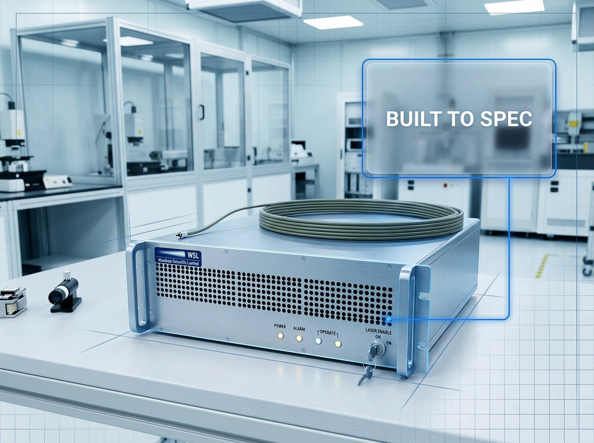
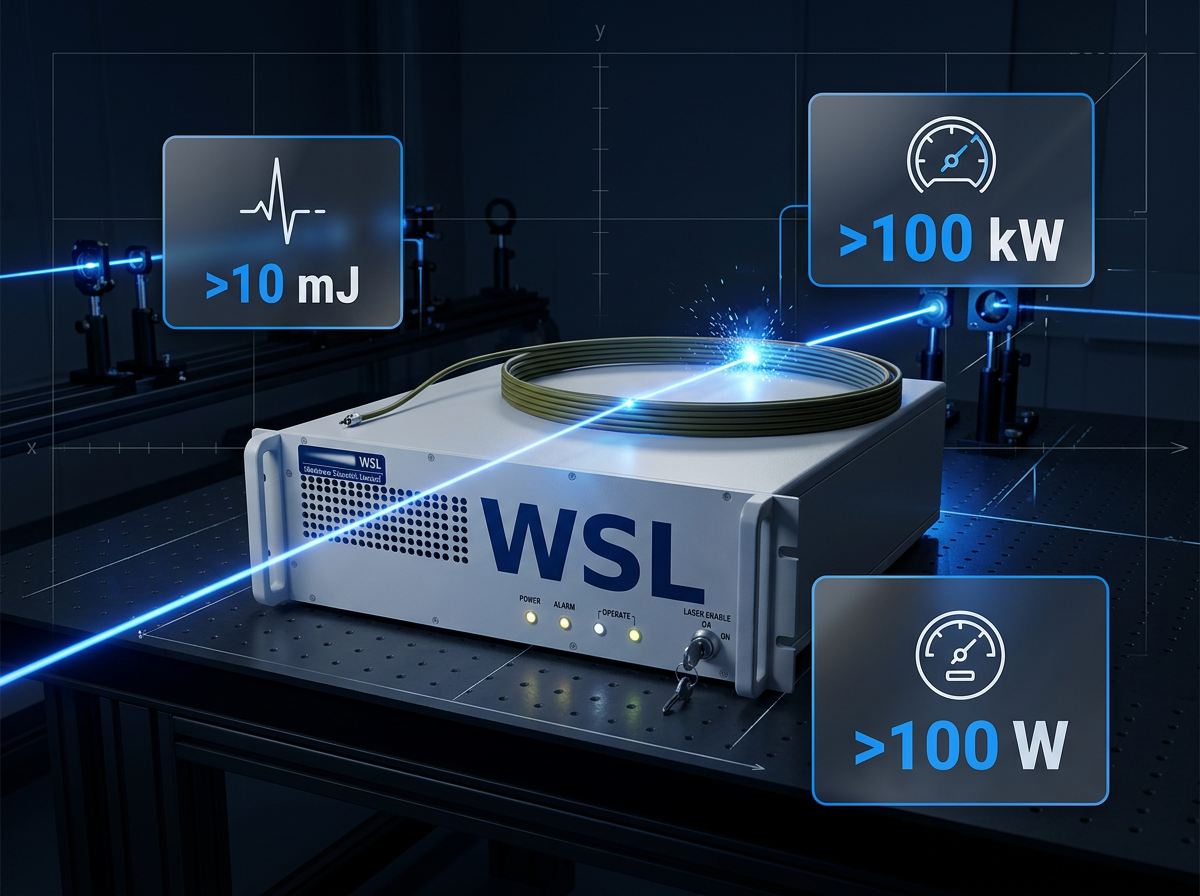
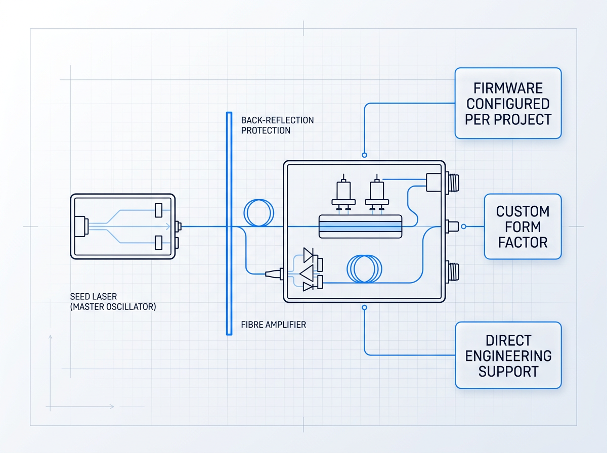
This erbium-doped fibre amplifier reaches the leading commercially available power levels for erbium fibre: pulse energies above 10 mJ, peak powers above 100 kW, and average powers above 100 W. The MOPA architecture — master oscillator power amplifier — keeps the seed laser independent of the power stage, so pulse format and spectral properties are preserved as output scales. All three figures are configurable per project: the platform is sized to your requirement, not to a fixed catalogue SKU.
Configurable Across Every Specification Dimension
Only the erbium physics and the platform are fixed. Every other parameter — operating band, output power, pulse regime, cooling, form factor, and control firmware — is specified per project.
Operating Band
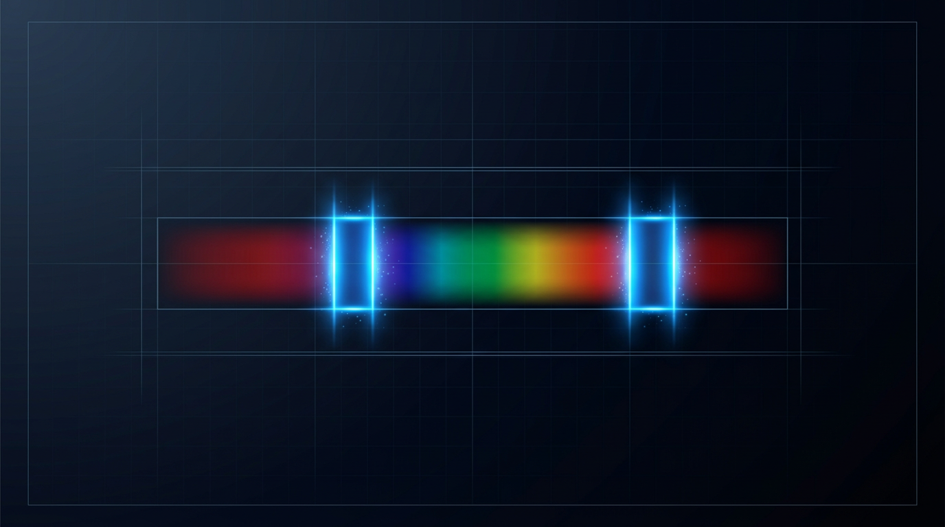
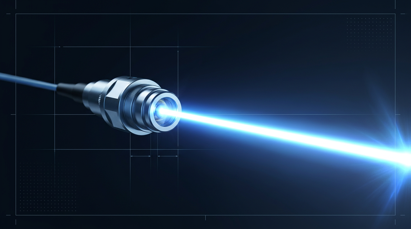
C-band, L-band, or dual C+L from a single source through one cable.
Output Power
Specified per project, from research-level to the highest commercially available erbium-fibre powers.

Pulse Regime
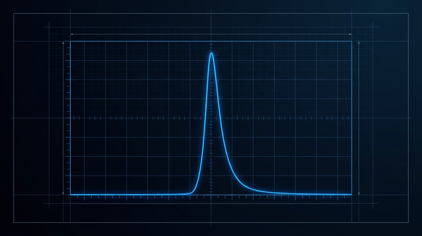
CW, short-pulse (e.g. 100–500 ns), or custom — matched to temporal requirements.
Pulse Energy and Peak Power
Specified per project; scalable to above 10 mJ and above 100 kW.
Cooling
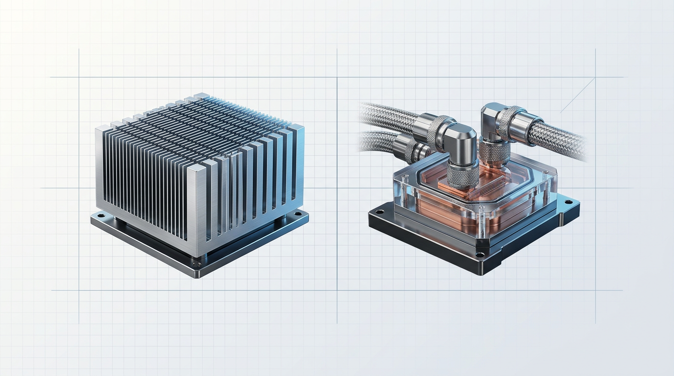
Air- or water-cooled, matched to thermal budget and deployment environment.
Form Factor and Delivery Cable
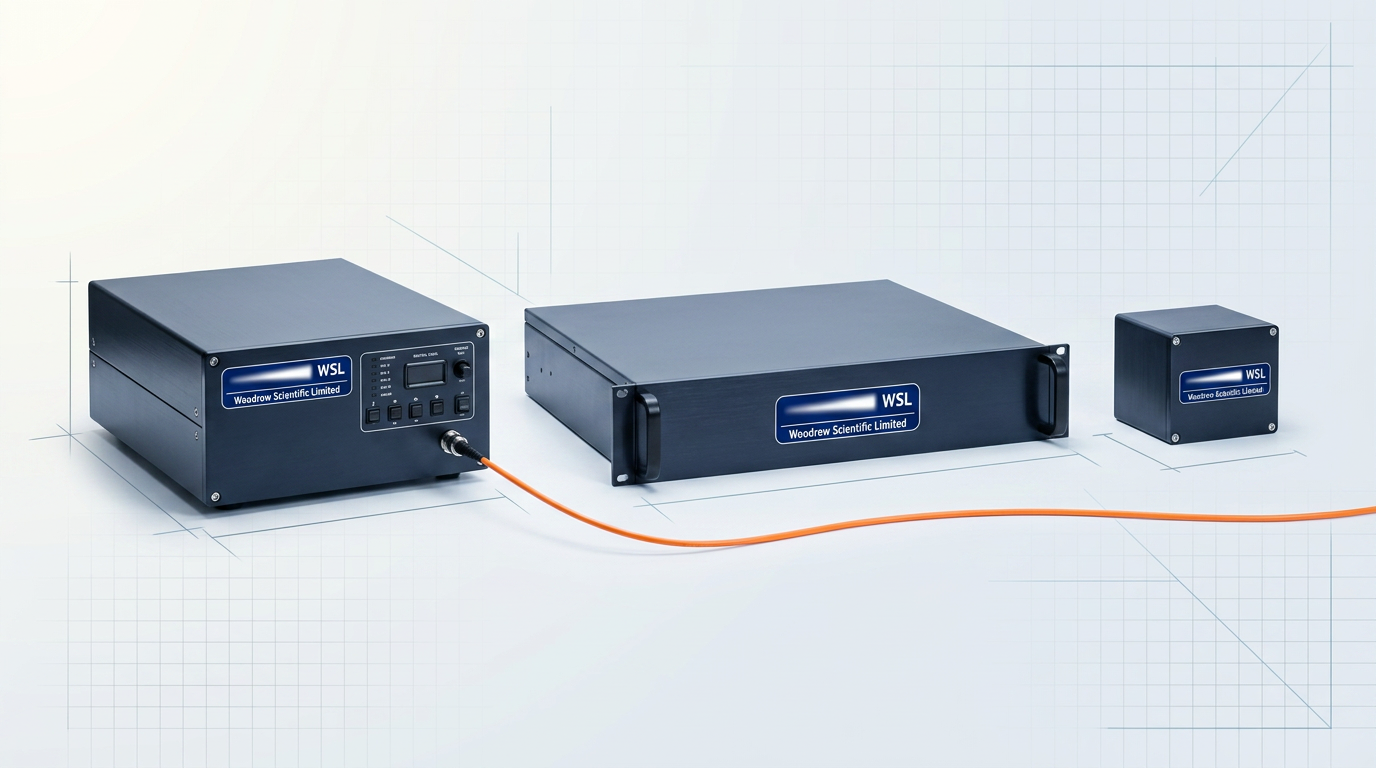
Benchtop, rack, or OEM module; cable length and termination specified per project.

Control Firmware and Comms
Custom firmware and communication standards specified per project for your control setup.
Why 1550 nm Is the Informed Wavelength Choice
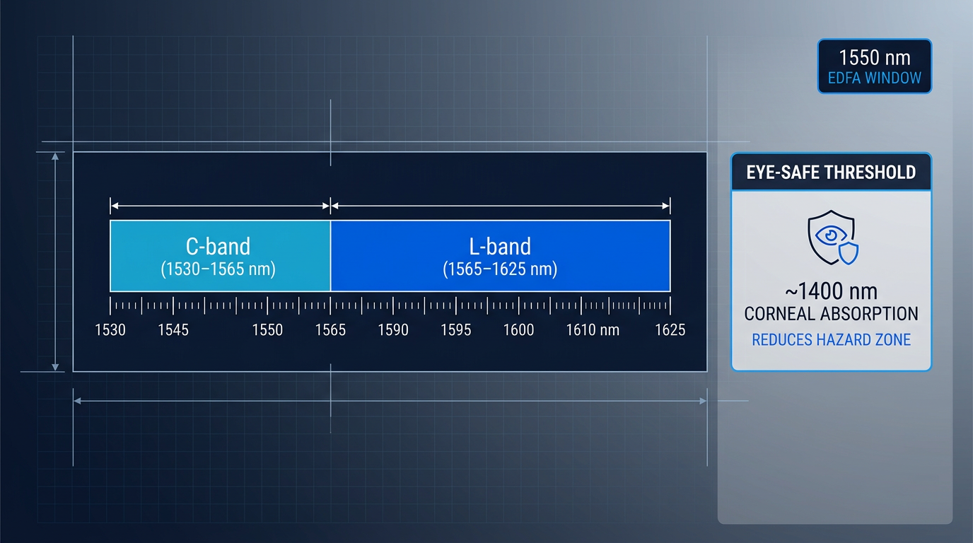
The erbium-fibre window spans 1530–1625 nm, covering the C-band (1530–1565 nm) and L-band (1565–1625 nm). Above approximately 1400 nm, the cornea and lens absorb incident light before it reaches the retina, raising the maximum permissible exposure significantly versus 1064 nm sources — a physical advantage, not a marketing claim. The Custom EDFA offers reduced-hazard-zone builds for deployments where a 1064 nm source would demand larger exclusion zones. LiDAR, quantum sensing and communications, FSOC, and distributed sensing converge on this band: high power, beam quality, and an eye-safer wavelength make 1550 nm the deliberate choice for new system designs.
Applications: Where the Custom EDFA Performs
From LiDAR and quantum photonics to surface processing and OEM laser builds, the Custom EDFA is configured per application — not adapted from a catalogue part.
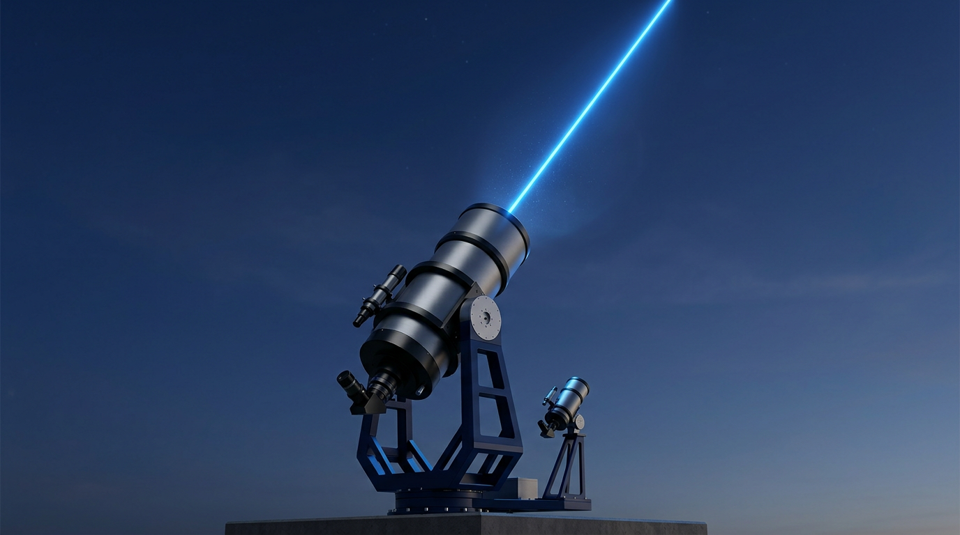
Free-Space Optical Communications (FSOC)
Ground-station uplink and beacon amplification, with the EDF-UL-10 as a reference FSOC uplink configuration and output configurable per link budget.
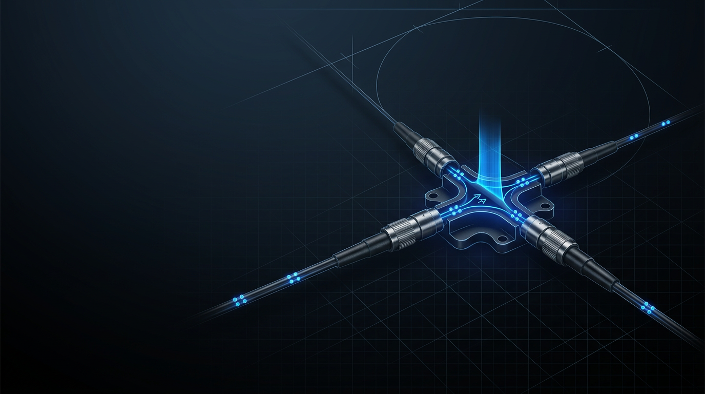
Quantum Sensing and Communications
Low-noise, configurable C-band amplification matched to quantum photonics requirements, where telecom and quantum infrastructure converge at 1530-1565 nm.
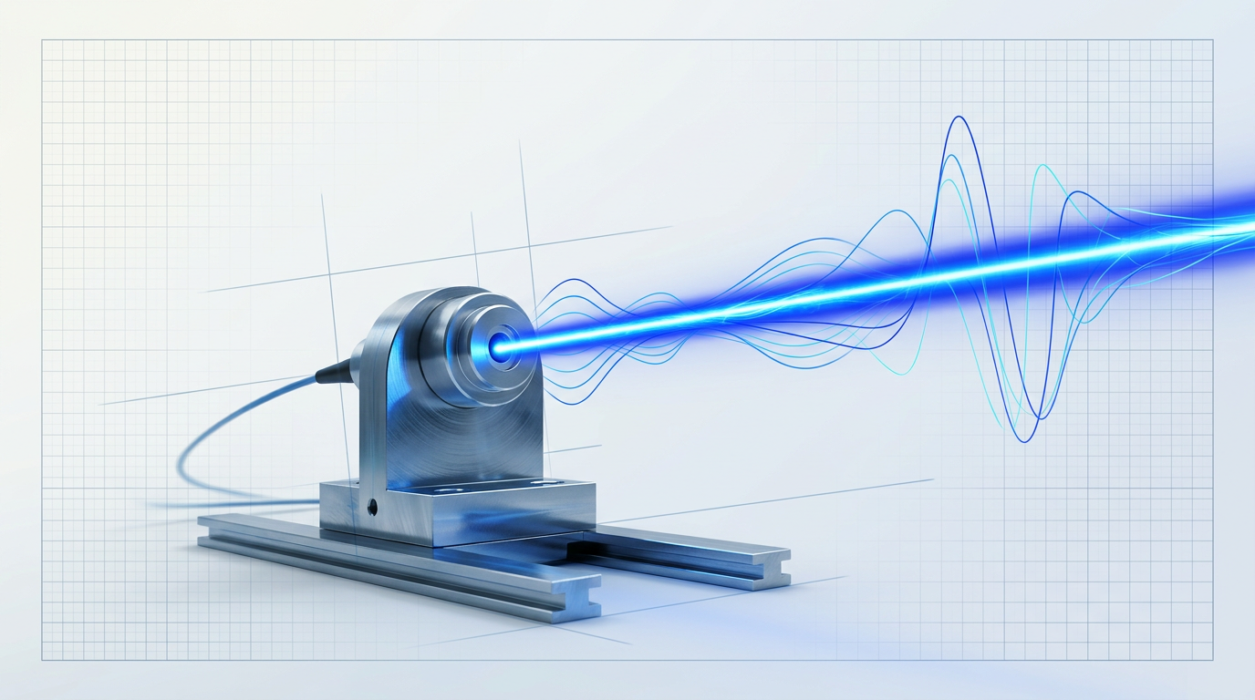
Defence and Directed-Energy Research
High pulse energy and peak power at eye-safer wavelengths, with configurable pulse regime and cooling matched to demanding programme requirements.
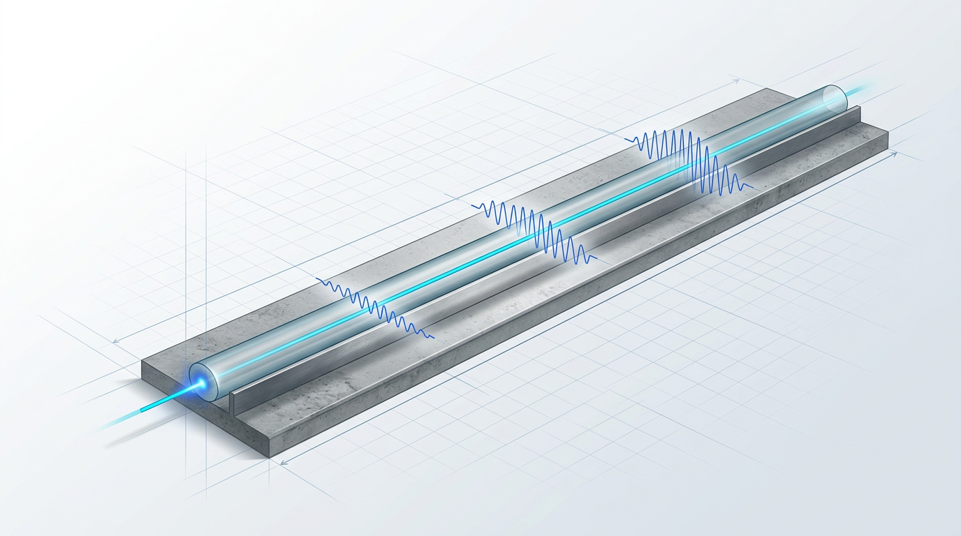
Fibre Sensing: DAS and Structural Monitoring
High-power pulsed 1550 nm amplification for distributed acoustic sensing and structural monitoring over long fibre spans, with pulse regime configured per system.
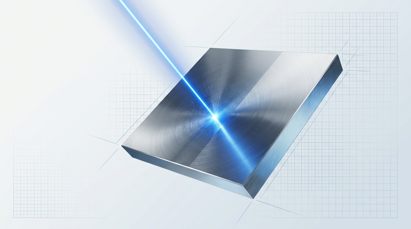
Surface Processing: Cleaning, Marking, and Texturing
Short-pulse, high-peak-power erbium-fibre source for cleaning, paint removal, texturing, and marking — the EDF100 is a reference short-pulse configuration.
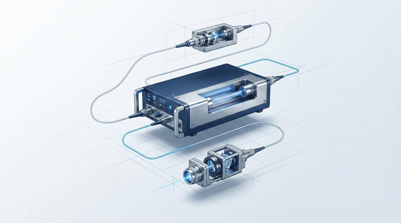
OEM Laser System Builds
Integrate the Custom EDFA as the amplifier core of your own laser product — cleaning machines, industrial processing systems, or other OEM builds.
See the Custom EDFA in Your Application
From FSOC ground-station uplinks to LiDAR and quantum photonics, every Custom EDFA is configured to the application. Explore the full product range to find your starting point.

Built in the UK, on Patented Technology, by the Inventors
WSL designs, builds, qualifies, and supports every amplifier in-house in Southampton — on patented technology, not licensed or imported designs. Founded in 2012, the team's fibre-amplifier expertise traces directly to Southampton's Optoelectronics Research Centre, the birthplace of the EDFA, with over 200 years of combined engineering experience behind it. That lineage has a practical consequence: the engineers who designed your amplifier are available to modify firmware, resolve integration issues, and address field problems at source. Many EDFA suppliers are resellers or importers who structurally cannot offer this. CE and UKCA certified; supplied worldwide.
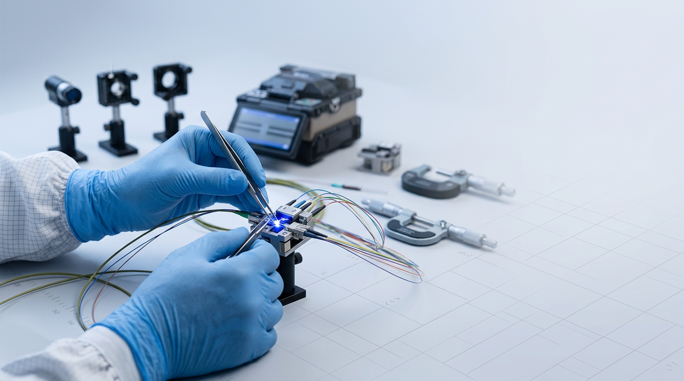
Integration, Back-Reflection Protection, and Control Interfaces
Control firmware and communication standards are configured per project — the amplifier interfaces with your existing control infrastructure, not the other way around. The physical integration envelope is equally a specification parameter: the unit is built to fit from the outset. The MOPA architecture provides structural isolation between the seed laser and the power stage, and our in-house design capability means back-reflection protection is engineered to your specific seed and topology. The same engineers who built your amplifier remain engaged through commissioning — integration support is part of the product, not an afterthought.
Ready to Discuss Your EDFA Requirements?
Every Custom EDFA is configured per project. Share your application, power level, control interface, and integration constraints with our engineering team to get started.
Erbium Doped Fiber Amplifier: Frequently Asked Questions
Technical and commercial questions for buyers evaluating the Custom EDFA against specification requirements.
The Custom EDFA covers the C-band (1530–1565 nm), L-band (1565–1625 nm), or dual C+L — both bands delivered from a single source through one cable. Operating band is a configurable parameter specified per project, not a fixed catalogue choice. Dual C+L delivery through a single cable removes the need for a second amplifier entirely, simplifying system architecture and reducing integration complexity.
The Custom EDFA reaches average powers above 100 W, pulse energies above 10 mJ, and peak powers above 100 kW — at the leading commercially available levels for erbium fibre. Every unit is configured to the application, so exact figures are specified per project rather than drawn from a fixed datasheet. These power levels are the result of the MOPA architecture and WSL's in-house engineering, scaled to what the application demands.
The Custom EDFA supports CW, short-pulse (for example, 100–500 ns), and fully custom pulse regimes. Pulse regime is a configurable parameter matched to the application — formats beyond the named examples are available where the application requires them. The pulse format is defined at the seed stage of the MOPA architecture and scaled by the amplifier, so temporal and spectral characteristics set by the seed are preserved as output power is increased.
Thorlabs catalogue EDFAs — including the EDFA100 and EDFA300 series, available as benchtop units and PXIe modules — are fixed-specification, off-the-shelf products designed for sub-watt output power. They serve well-defined, general-purpose use cases. The Custom EDFA is a different category of product: it is engineered end-to-end to the application across operating band, output power, pulse regime, cooling, form factor, and control firmware, reaching power classes orders of magnitude higher — above 100 W average, above 100 kW peak, above 10 mJ pulse energy. The distinction is not only power; it is the depth of per-project customisation and the in-house engineering model that makes it possible.
MOPA stands for master oscillator power amplifier. It separates the seed laser — which defines pulse format, wavelength, and spectral properties — from the power amplifier stage, which scales output power independently. The practical consequence is that pulse quality is preserved at high output levels: the seed sets the temporal and spectral characteristics, and the amplifier scales power without degrading them. This matters for applications requiring both high power and precise pulse control, including LiDAR, fibre sensing, and surface processing.
At wavelengths above approximately 1400 nm, the cornea and lens of the eye absorb incident light before it reaches the retina. This raises the maximum permissible exposure (MPE) significantly compared to 1064 nm sources, where the beam can transmit through the ocular media and focus on the retina. The result is a smaller Nominal Hazard Zone at 1550 nm than at 1064 nm for equivalent output power — a well-established laser safety classification difference, not a safety guarantee. The Custom EDFA supports reduced-hazard-zone builds for applications where this classification advantage is operationally relevant.
Every unit is configured per project, so the process begins with submitting your requirements for a specialist evaluation. WSL will assess feasibility and provide a quotation; direct engineering support continues from quotation through to integration. There is no off-the-shelf stock lead time — timelines are established once the specification is defined. To make the evaluation as efficient as possible, it helps to share your target application, operating band, output power, pulse regime, pulse energy and peak power targets, cooling preference, form factor constraints, and control interface requirements.