

What an EDFA Must Do in a DWDM Link
In a DWDM system, a single EDFA amplifies the entire channel comb simultaneously in the optical domain, with no OEO conversion. The challenge: erbium gain is inherently non-uniform across the band, and ASE accumulates across cascaded stages, compounding the OSNR penalty on every channel.
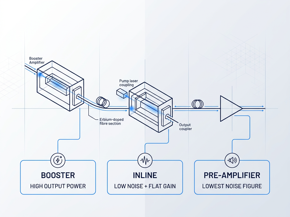
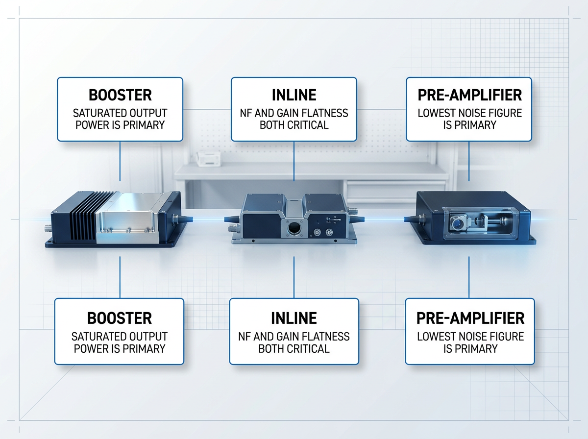
Placement determines the primary performance priority. A booster demands high saturated output power; an inline amplifier requires low noise and flat gain; a pre-amplifier demands the lowest achievable noise figure.
These roles map to three specification axes: gain flatness, noise figure, and output power, each addressed in depth below.
Uniform Gain Across All Channels
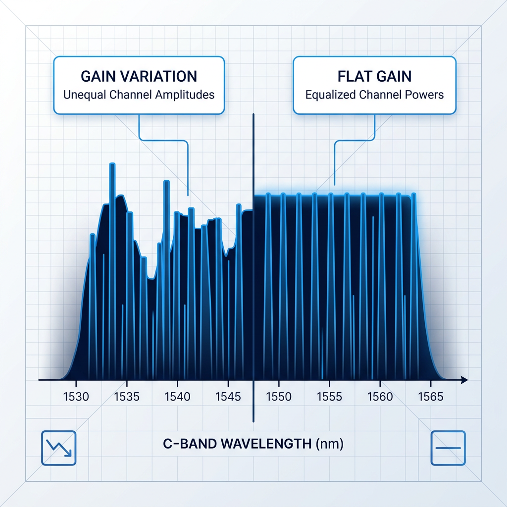
EDFA gain is inherently wavelength-dependent: untreated, different channels in the comb receive different gain. In a cascaded multi-span link, this imbalance compounds span by span — channels that receive more gain accumulate excess power and risk nonlinear effects, while under-amplified channels lose OSNR margin. Neither outcome is recoverable downstream.
Specify gain flatness as a peak-to-peak variation figure across your full channel plan, not just at a single operating point. The tighter the variation, the more headroom you retain over the full link.
Noise Figure and OSNR Budget
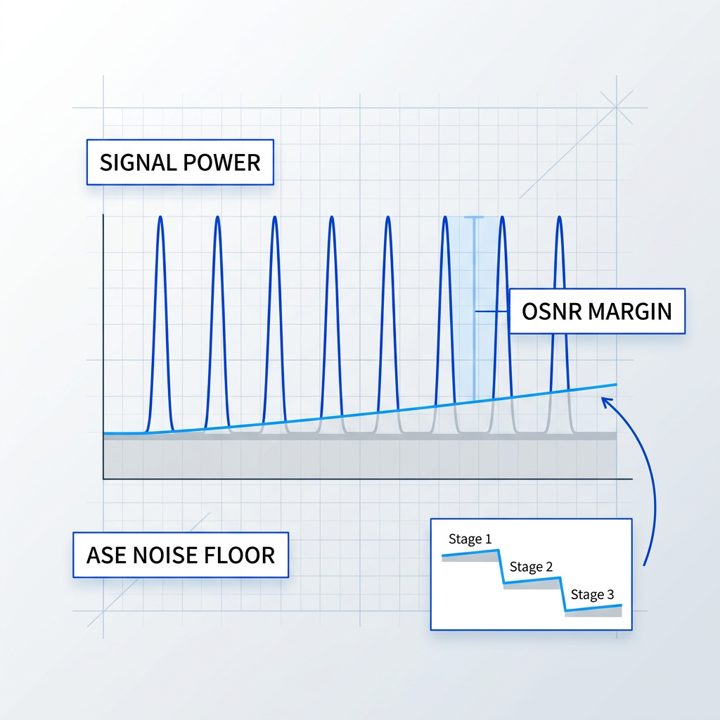
Amplified spontaneous emission (ASE) is the dominant noise mechanism in an EDFA. Noise figure (NF) quantifies the OSNR degradation introduced per amplifier stage. Because NF penalties accumulate across every inline stage and cannot be filtered out, they set an ultimate limit on how many spans can be cascaded and therefore on link reach.
The Cisco DWDM planning guide identifies a noise figure below 6.0 dB as a meaningful design target. Specify NF at your operating gain point; a high NF at any stage permanently degrades the OSNR budget for every span that follows.
Output Power and Span Budget
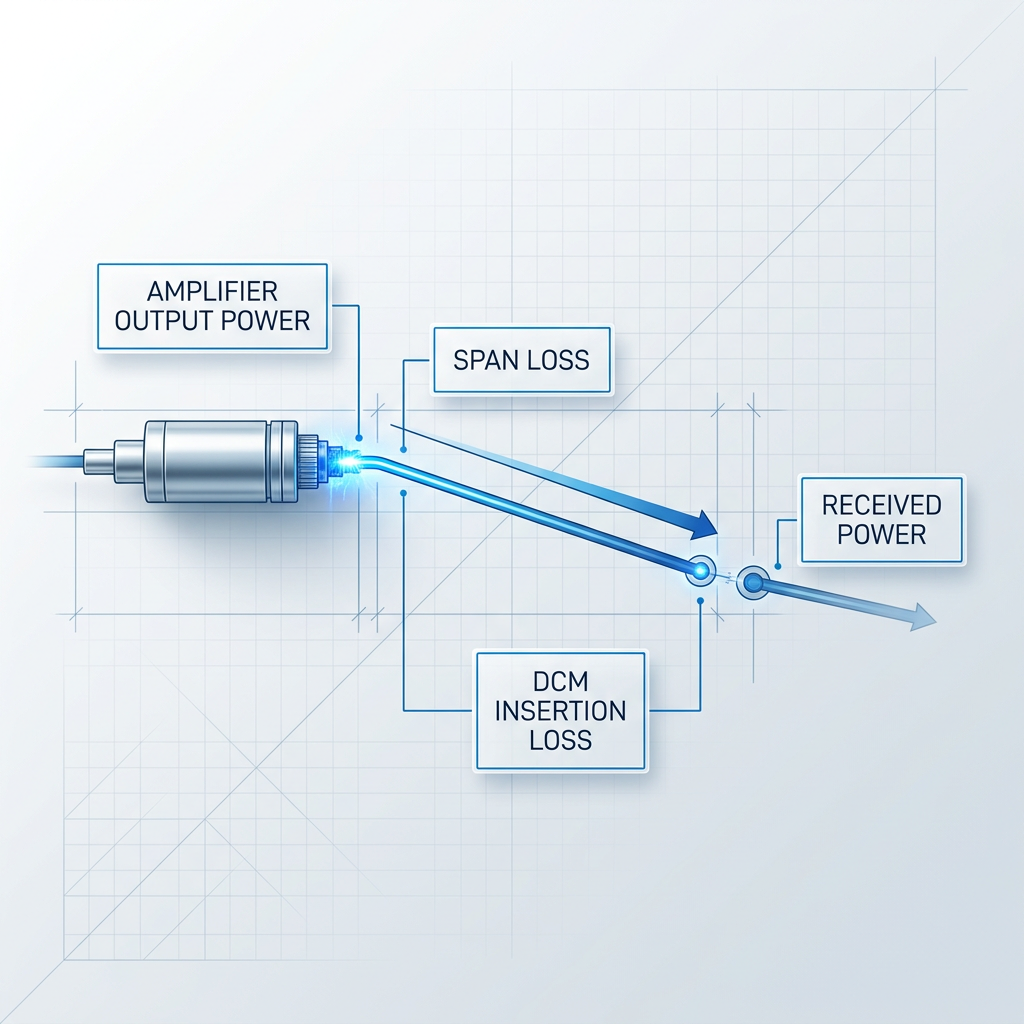
Output power must be sufficient to overcome the total span loss — fibre attenuation, connector and splice losses, and insertion losses from any mid-stage elements such as dispersion compensation modules or OADMs — and still deliver adequate signal power to the next stage.
A mismatch between amplifier output and span budget forces workarounds such as additional attenuators or extra amplifier stages, each of which costs OSNR and system margin. Specify output power against a full link loss budget that accounts for all passive elements in the signal path, not fibre loss alone.
C-Band, L-Band, or Dual C+L
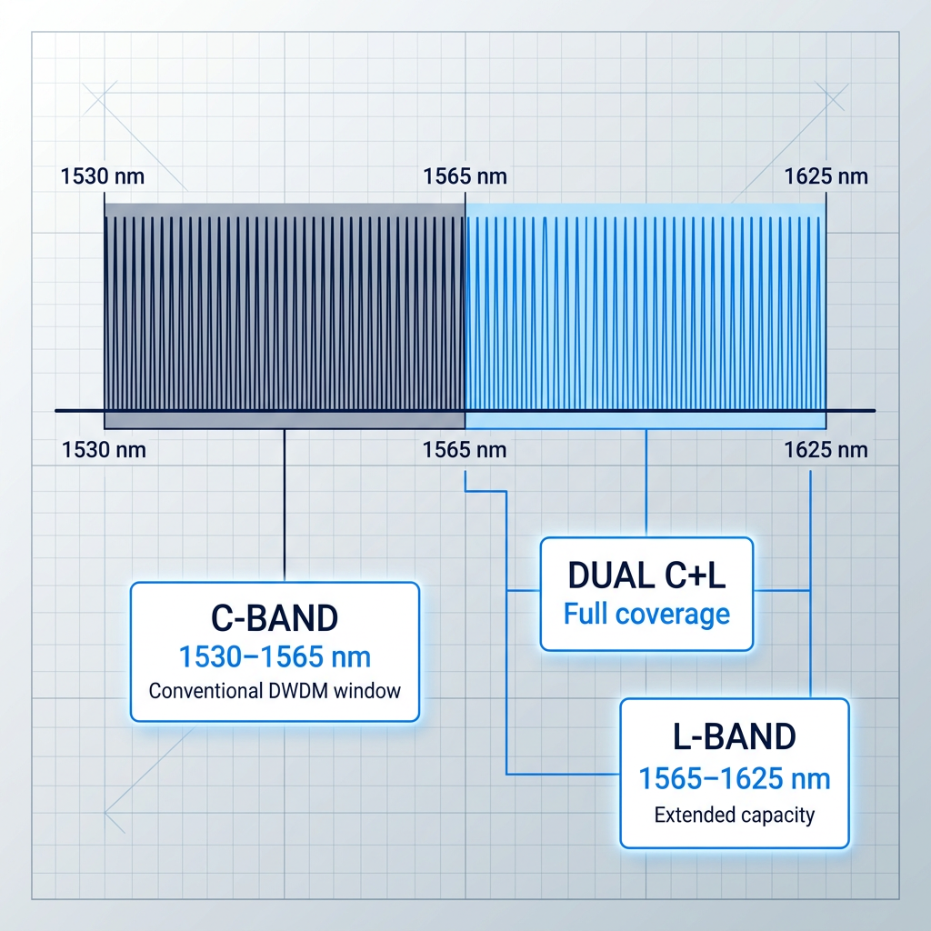
Band choice determines amplifier architecture: C-band (1530–1565 nm) is the conventional DWDM window; L-band (1565–1625 nm) extends capacity where C-band is exhausted or where fibre nonlinearities favour longer wavelengths; dual C+L covers both simultaneously. Each band requires a different EDF length, pump configuration, and gain-flattening design — they are not interchangeable.
Channel spacing and count within each band are governed by the ITU-T G.694.1 frequency grid. Specify the band your system requires; the amplifier architecture follows from that choice. Band and channel count are covered in greater depth in the next section.
Constant Gain vs Constant Power
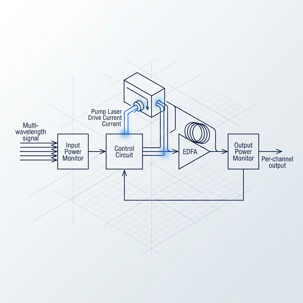
In constant gain mode, the amplifier holds its gain setpoint fixed when input power changes. When channels are added or dropped — as in a reconfigurable OADM network — surviving channels do not experience a power surge. In constant output power mode, total output is held fixed, which suits certain booster applications.
Constant gain is the standard mode for inline amplifiers in networks with channel add/drop. Specify the control mode your network architecture requires; the wrong choice can cause large power imbalances between channels at the receivers.
Saturated Output Power Is Primary
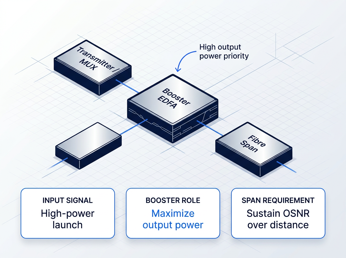
The booster sits immediately after the transmitter or multiplexer, at the head of the first fibre span. ITU-T G.663 defines it as a high saturation-power device used directly after the optical transmitter to increase signal power level, and notes it does not need stringent noise requirements — because the signal enters at high power, ASE contribution from this stage is diluted by subsequent amplification.
Saturated output power is the dominant specification axis. The amplifier must launch sufficient power into the span to sustain OSNR over its full length. Noise figure is a secondary concern here, unlike in every subsequent stage.
NF and Gain Flatness Both Critical
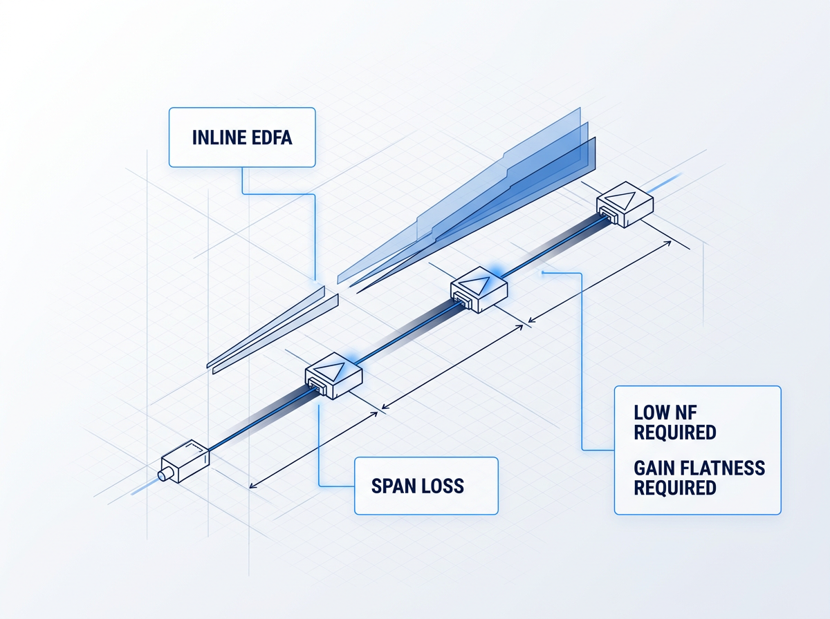
The inline (line) amplifier sits between fibre spans, compensating loss at each intermediate node. This is the most specification-demanding role: noise figure and gain flatness are both critical because ASE accumulates additively across every cascaded stage and any degradation is unrecoverable.
Noise level must be minimal — any noise is magnified by all subsequent amplifiers. Output power must be matched to span loss to maintain the link budget. Specification errors here compound through the entire link, making this the role where getting the parameters right matters most.
Lowest Noise Figure, Moderate Gain
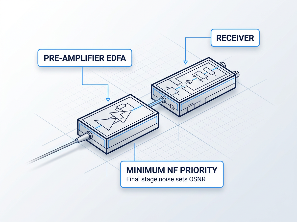
The pre-amplifier sits immediately before the receiver, boosting the incoming signal to improve receiver sensitivity. ITU-T G.663 defines it as a very low noise device used directly before the optical receiver. As the final amplification stage, its noise contribution directly determines the OSNR at the decision circuit — there is no subsequent stage to dilute it.
Noise figure is the primary specification axis. Gain is typically moderate; the signal travels no further after this stage, so output power is a secondary concern. Specify the lowest achievable NF first, then size the gain to meet receiver sensitivity requirements.
Two Stages, One Preserved NF
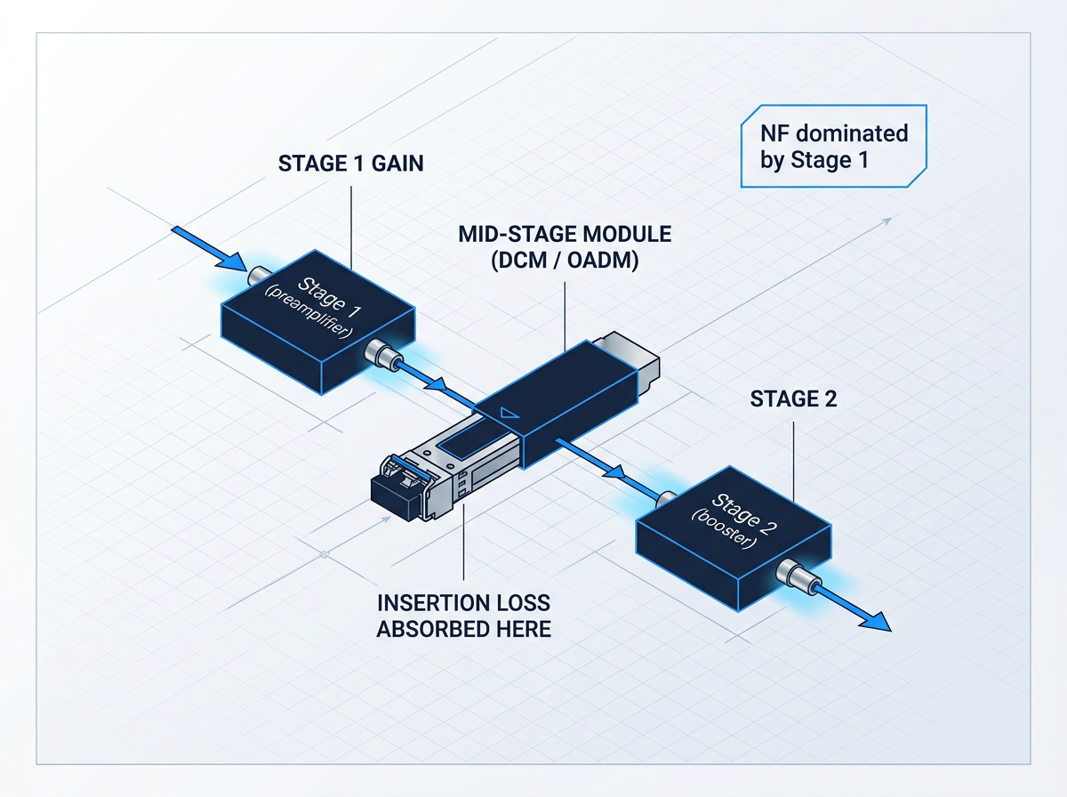
A two-stage amplifier with mid-stage access allows dispersion compensation modules (DCMs) or optical add/drop multiplexers (OADMs) to be inserted between the gain stages. Placing a lossy element after a single-stage amplifier forces the signal into the next amplification site at reduced power, worsening the overall noise figure.
The two-stage architecture absorbs that insertion loss between stages. Total NF is governed primarily by the first-stage gain — the higher that gain, the smaller the second stage's noise contribution. This design is the standard solution for long-haul links and reconfigurable networks requiring dispersion management or wavelength add/drop.
Role First, Then Specify
Before fixing output power target, NF target, and gain range, confirm which role the amplifier will fill. A unit optimised for booster duty — high saturated output power, relaxed NF — is not the right choice for a pre-amplifier position, where the lowest achievable NF governs receiver sensitivity. The inline role demands both simultaneously.
Each placement has a distinct performance hierarchy. Specify to that hierarchy, not to a generic set of figures, and the amplifier will be sized correctly for the link it serves.
The Standard DWDM Window
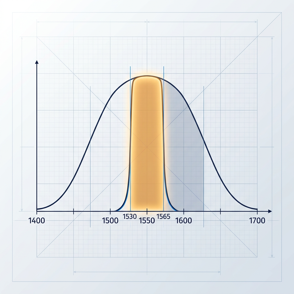
The C-band (1530–1565 nm) is the conventional DWDM amplification window and the default choice for most deployments. It coincides with the lowest attenuation region of standard singlemode fibre and sits squarely within the erbium gain bandwidth. ITU-T G.694.1 places DWDM channels on a fixed grid anchored at 193.1 THz; at 100 GHz spacing the C-band supports 32 or more channels, with denser grids increasing that count further. For any DWDM link that has not yet exhausted C-band capacity, this is the natural starting point for amplifier specification.
Capacity Extension Beyond C-band
The L-band (1565–1625 nm) is the primary capacity-extension band, adding approximately 80 channels at 50 GHz spacing beyond what C-band alone provides. It becomes the preferred choice when C-band capacity is exhausted, or where dispersion-shifted fibre (DSF) networks suffer four-wave mixing nonlinearities that restrict C-band channel counts to fewer than ten. L-band amplification requires a distinct amplifier architecture: the EDF coil is four to five times longer than a comparable C-band design, and pump configuration differs accordingly. It is not a drop-in extension — it is a separate engineering decision.
Both Bands, One Cable
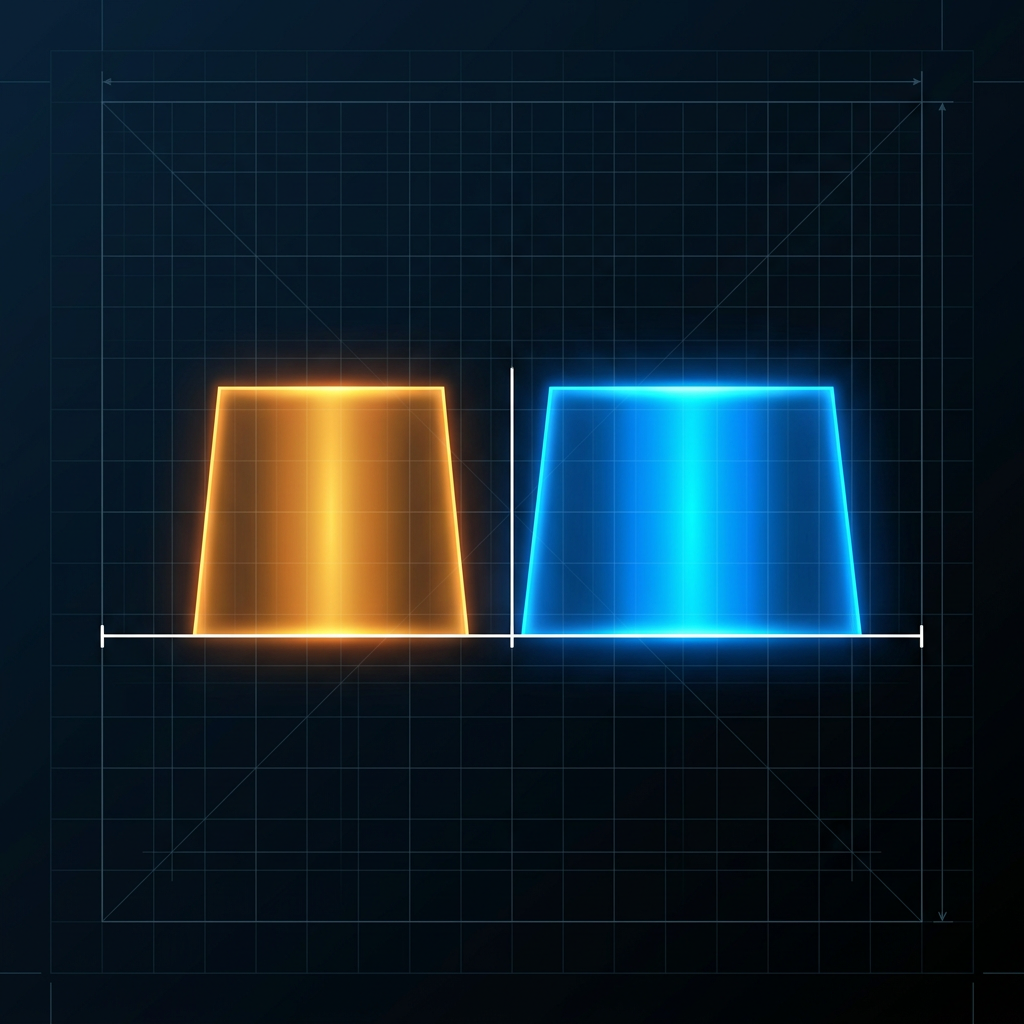
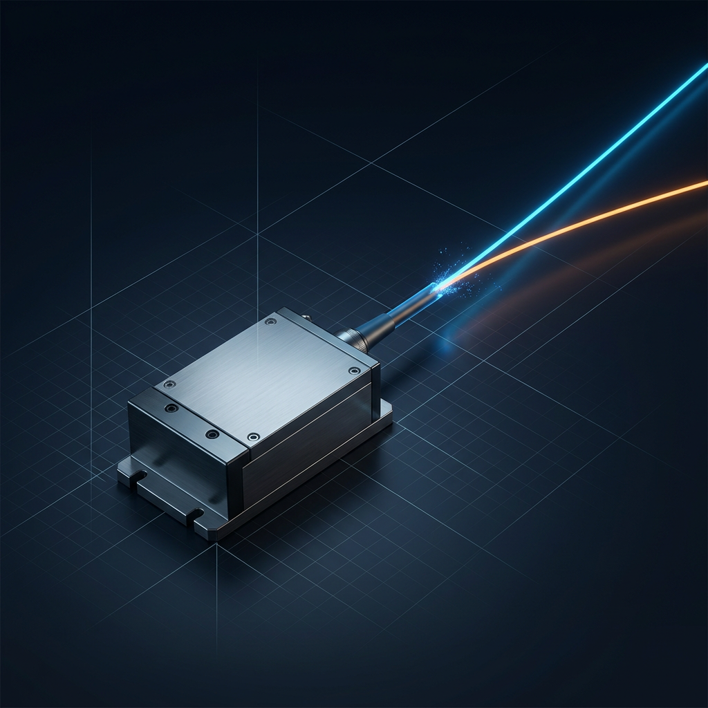
The WSL Custom EDFA delivers both C-band and L-band from a single source through one cable — no second amplifier required. This is the maximum-capacity configuration, effectively doubling the usable amplification window across the full 1530–1625 nm range.
Dual C+L operation requires a band-splitting architecture: the input signal is separated into its C-band and L-band components, each is amplified through an independently optimised gain section, and the outputs are recombined. Because both bands are handled within a single WSL unit, the integration envelope and cabling remain compact. Specify this configuration when total fibre capacity is the governing requirement.
ITU-T Grid and Spacing Options
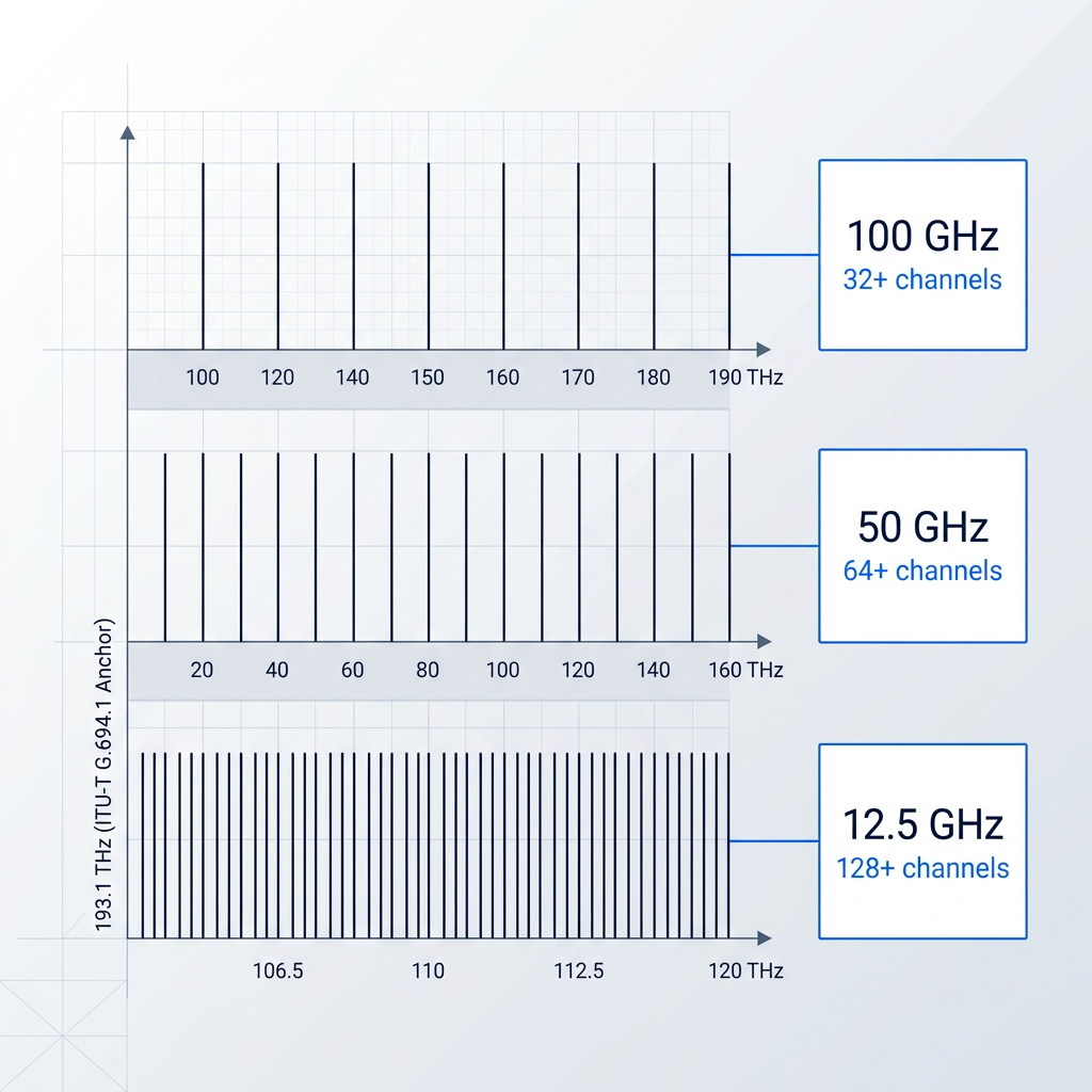
ITU-T G.694.1 defines the DWDM frequency grid anchored at 193.1 THz. Fixed-grid spacings range from 12.5 GHz (the tightest) through 25 GHz and 50 GHz to 100 GHz and wider (integer multiples of 100 GHz). A flexible grid is also defined, with nominal central frequency granularity of 6.25 GHz and slot-width granularity of 12.5 GHz, supporting mixed bit-rate and modulation-format allocations. For amplifier specification, tighter channel spacing increases channel count but places stricter demands on gain flatness and OSNR performance — both of which must be specified to the chosen grid.
Band Choice Shapes the Amplifier
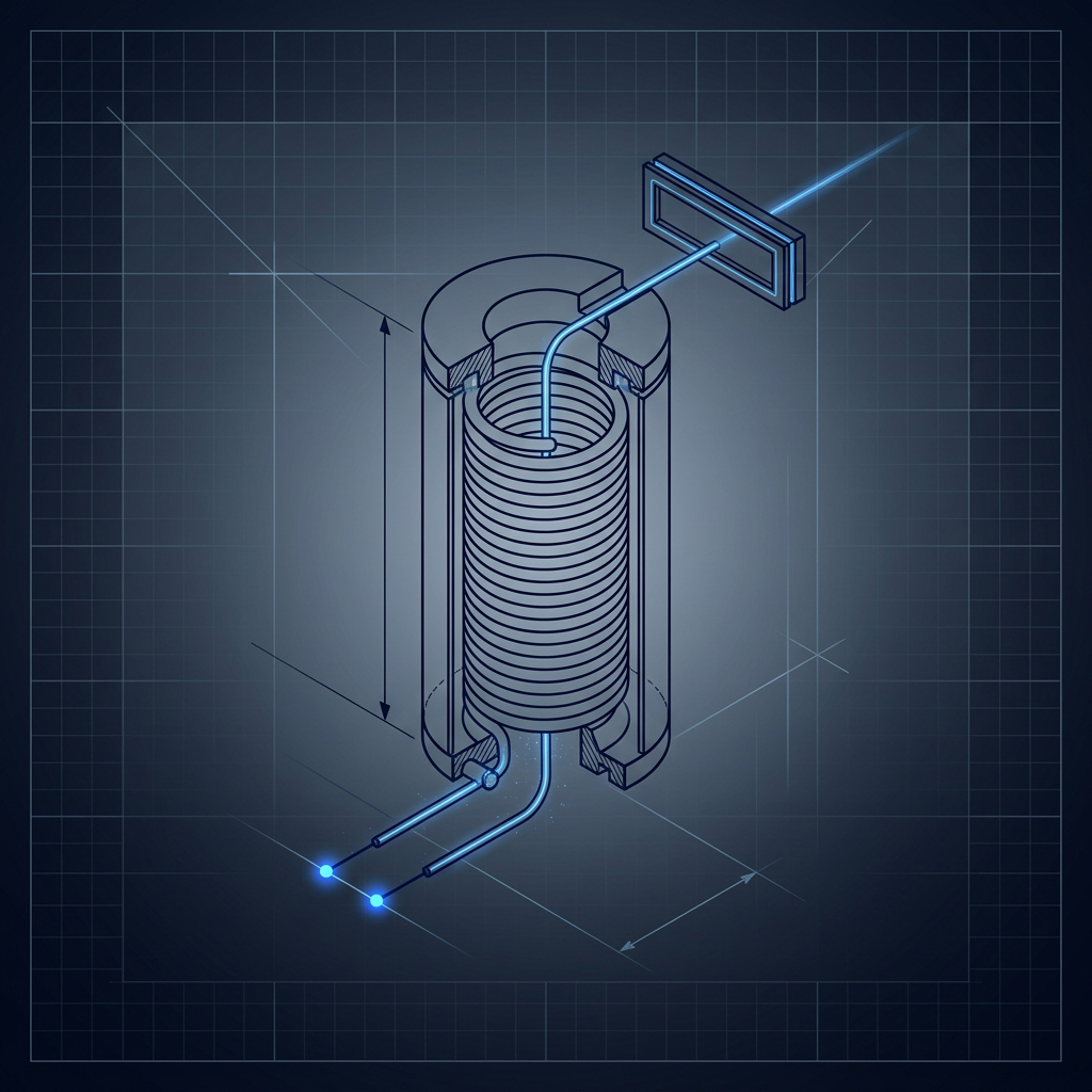
C-band, L-band, and dual C+L each demand a different amplifier: EDF length, pump architecture, and gain-flattening design all change with band selection. A unit configured for C-band is not adapted to L-band by adjusting a parameter — the gain sections, fibre lengths, and filter profiles are engineered to the band from the outset. Specifying the operating band is the first decision, upstream of every other parameter. The WSL Custom EDFA is built to the band you specify, not derived from a generic module — and the gain-flattening approach that follows is covered in the next section.
Why EDFA Gain Varies
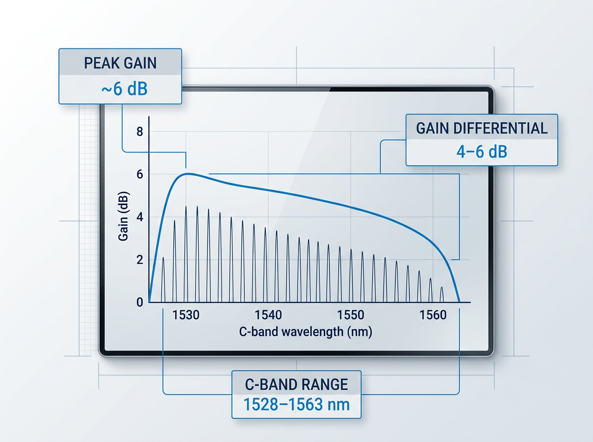
The gain an EDFA delivers is wavelength-dependent: the stimulated emission cross-section of erbium-doped fibre varies across the C-band, so different channels receive different gain. Lightwave Online notes that the gain per channel can vary by several dB as a function of wavelength across the transmission band. In a cascaded multi-span link, this imbalance compounds at every stage — channels receiving more gain accumulate excess power and risk nonlinear effects, while weaker channels suffer degraded OSNR. Every equalisation technique described in this section exists to correct this fundamental non-uniformity.
Gain-Flattening Filters
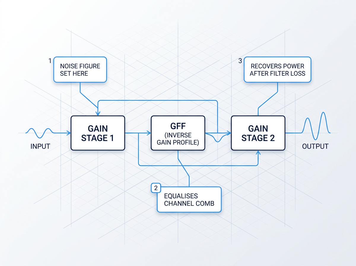
A gain-flattening filter (GFF) carries an inverse gain profile: it attenuates the channels receiving higher gain, levelling the comb. Gain-flattening filters introduce a wavelength-dependent loss of up to 8 dB at selected wavelengths; filters must be carefully matched to the amplifier architecture to achieve less than 1 dB gain variation. In a dual-stage amplifier, the GFF is placed mid-stage, between the two gain sections. Mid-stage placement preserves noise figure and output power — losses incurred there are recovered by the second gain stage, avoiding the penalties that would follow from filtering at the output.
Managing Gain Tilt
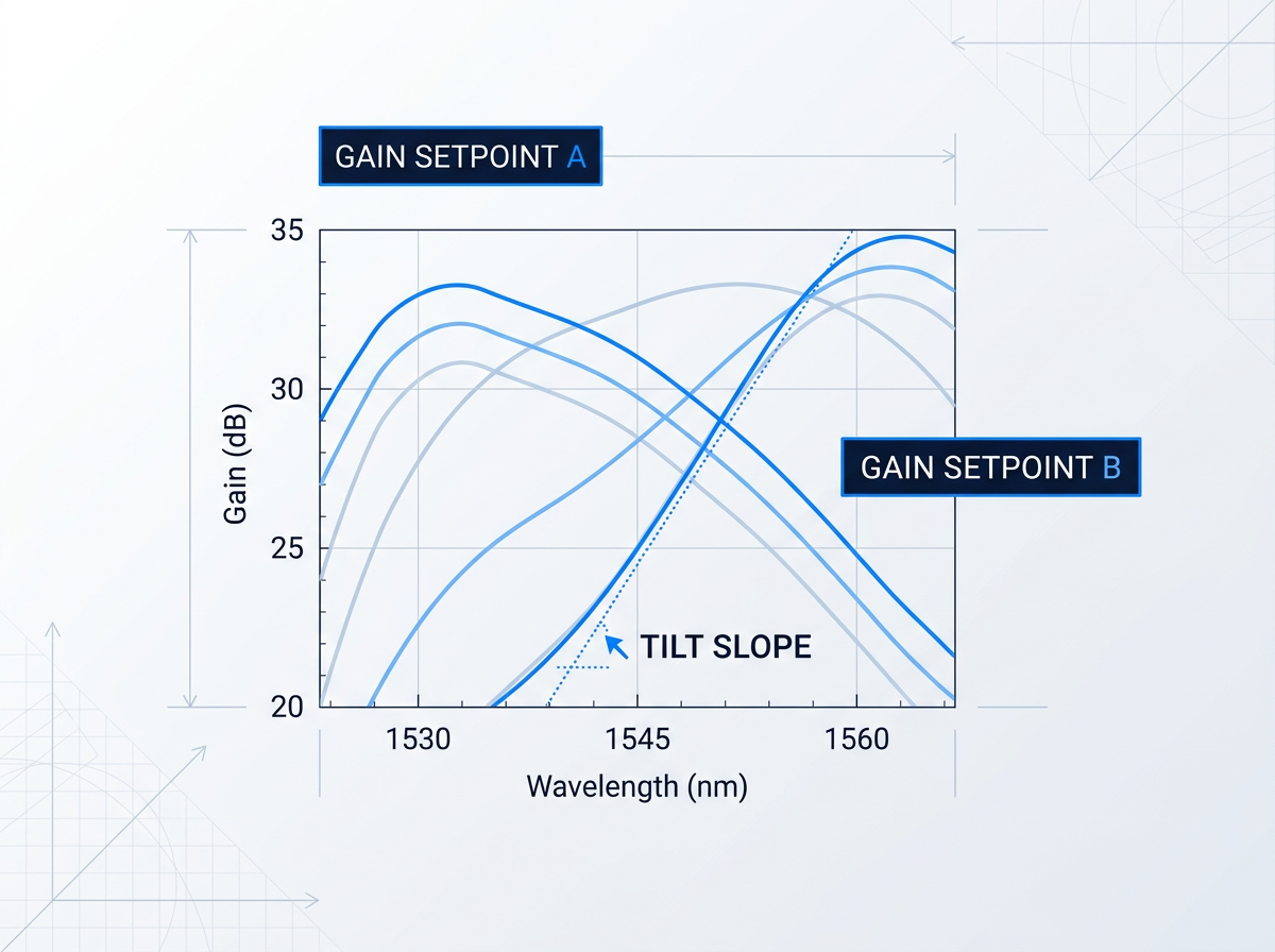
Gain tilt is a systematic slope across the channel comb that shifts as the amplifier's gain setpoint changes. In reconfigurable networks, channel add/drop events alter total input power, moving the gain setpoint and tilting the gain profile across surviving channels. A flatness specification written only at a single operating point will not catch this. Specify gain flatness as a peak-to-peak dB figure across the full operating gain range, not just at a nominal setpoint — this is the only way to ensure the amplifier performs correctly as channel loading changes throughout network life.
Tilt vs Ripple
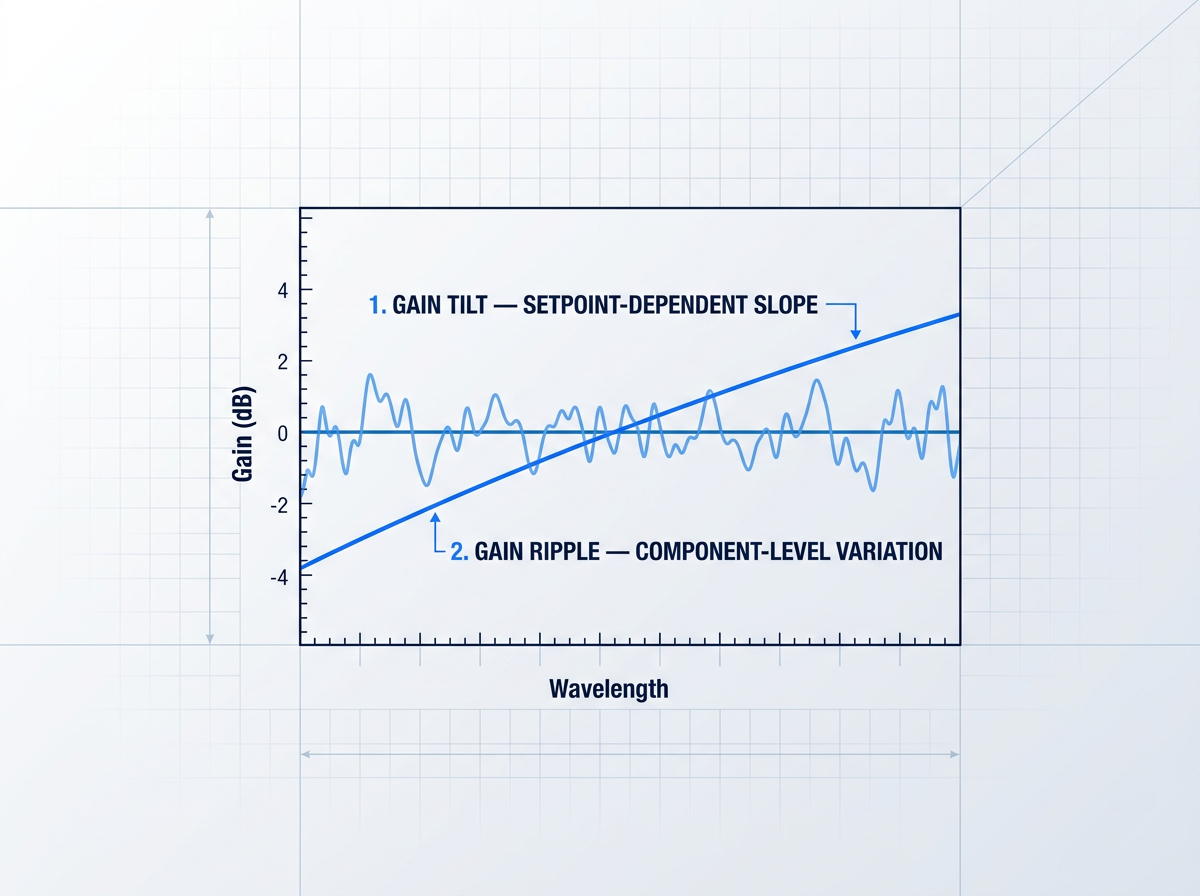
Where gain tilt is a systematic slope that tracks the gain setpoint, gain ripple is irregular, non-systematic spectral variation arising from component-level imperfections in the filter and fibre. Both must be within specification across the full channel plan: a flat mean gain that still carries significant ripple will deliver unequal power to individual channels. The two require different treatment — tilt is managed through the gain control loop, while ripple is addressed in filter design and component selection during amplifier manufacture.
Constant Gain Mode
In constant gain mode, a closed-loop control circuit adjusts pump power to hold the gain setpoint fixed as input power changes. Without this, an add/drop event that alters total input power will shift the gain and tilt the spectrum across surviving channels. WDM amplifiers for optical networking must be self-adjusting with flat wavelength response regardless of channel count or channel level. For any inline amplifier in a reconfigurable DWDM network, constant gain mode should be a standard specification requirement, not an optional feature.
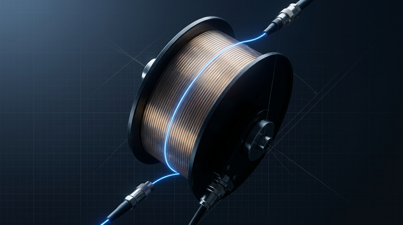
WSL Custom EDFA: Configurable Across Every Parameter
The erbium platform is fixed. Band, output power, cooling, form factor, cable, and control firmware are all specified per project — engineered to the application, not selected from a catalogue.
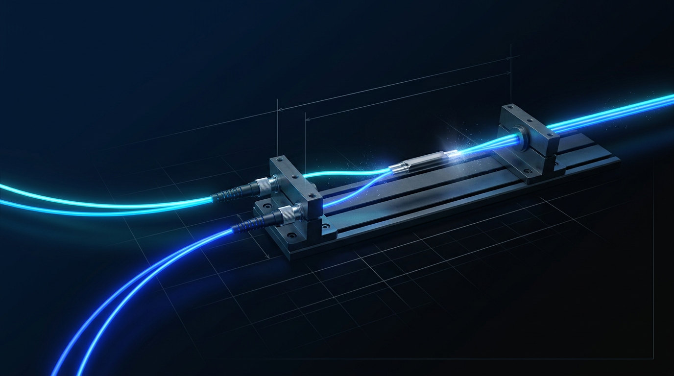
Operating Band: C-Band, L-Band, or Dual C+L
C-band (1530–1565 nm), L-band (1565–1625 nm), or both simultaneously — delivered from a single source through one cable, with no second amplifier required.
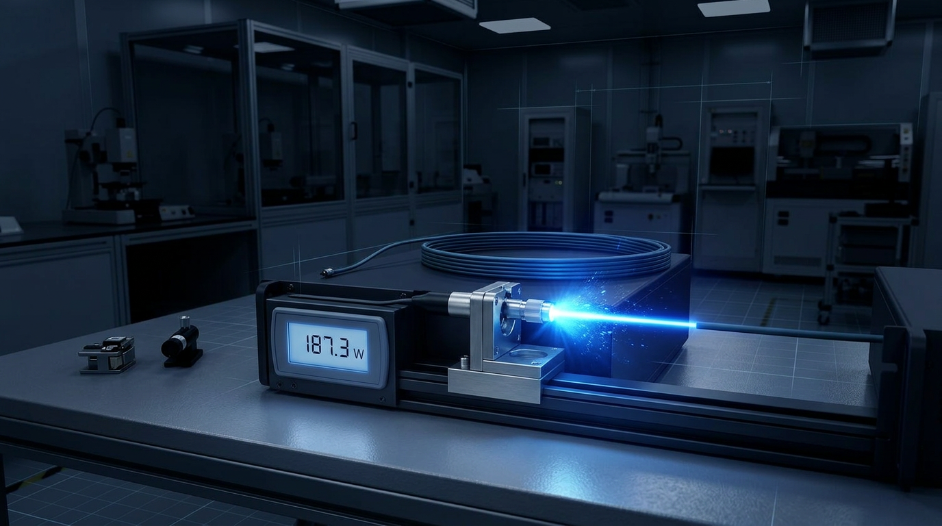
Output Power: Up to 200 W or More
Builds range from low-power units to 200 W or more average power, with output tunable from 0 to 100% of rated power.
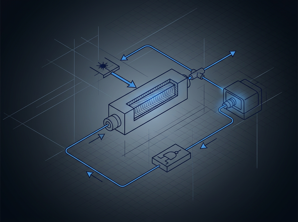
Architecture: MOPA on Erbium-Doped Fibre
Master oscillator power amplifier (MOPA) architecture on erbium-doped fibre, covering the full 1530–1625 nm C+L window in a single coherent platform.
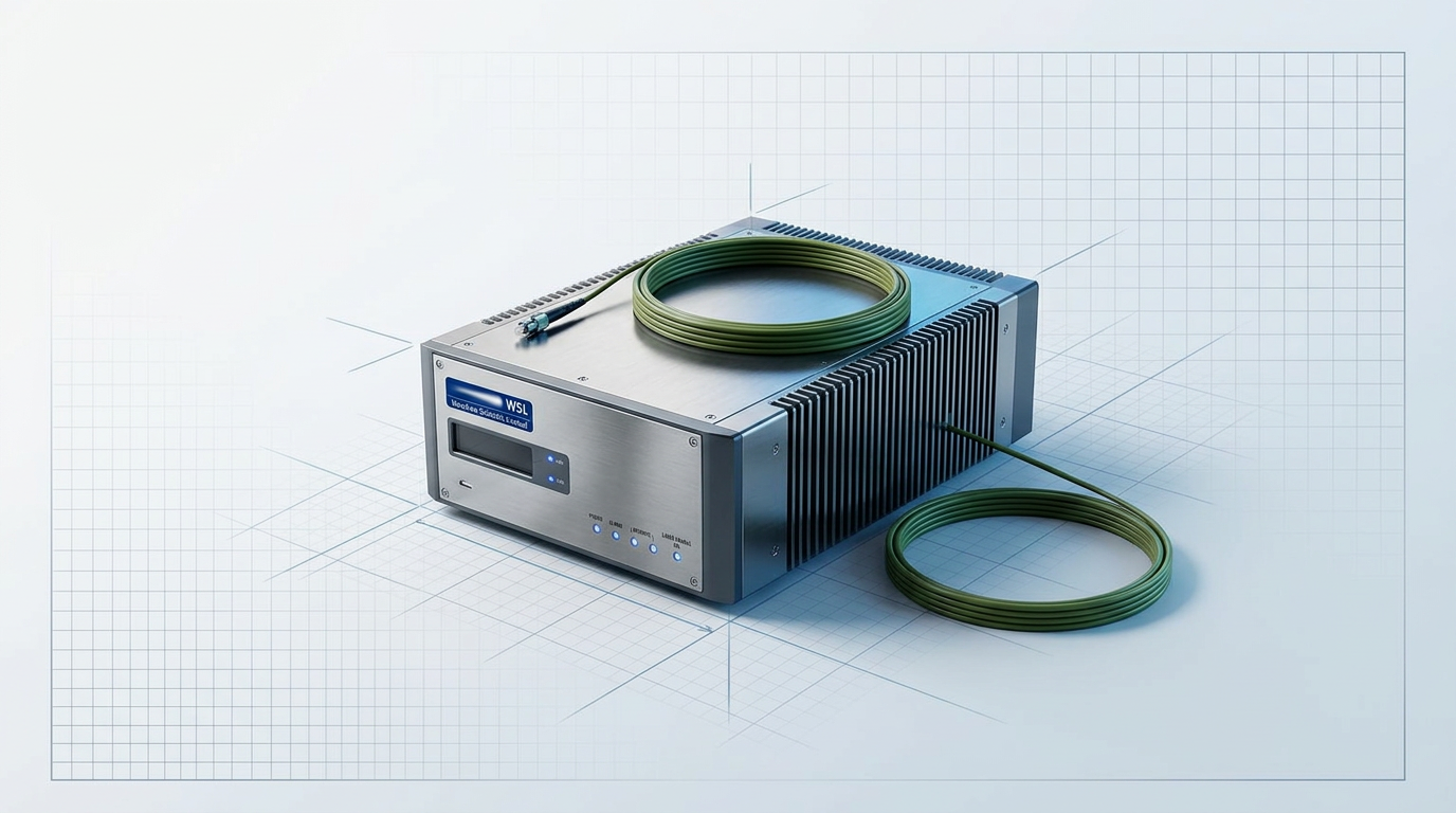
Cooling: Air-Cooled Standard, Water Cooling Available
Air-cooled as standard: no chiller or coolant loop required, simplifying system integration. Water cooling is available for installations where it is preferred.
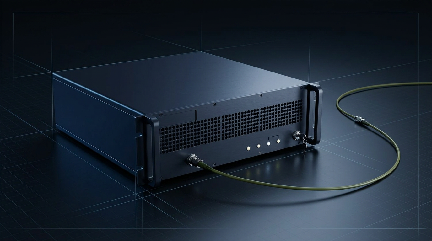
Form Factor and Delivery Cable Per Project
Form factor, delivery cable length, and termination are configured to the system. The physical integration envelope is specified to the application, not a fixed chassis.
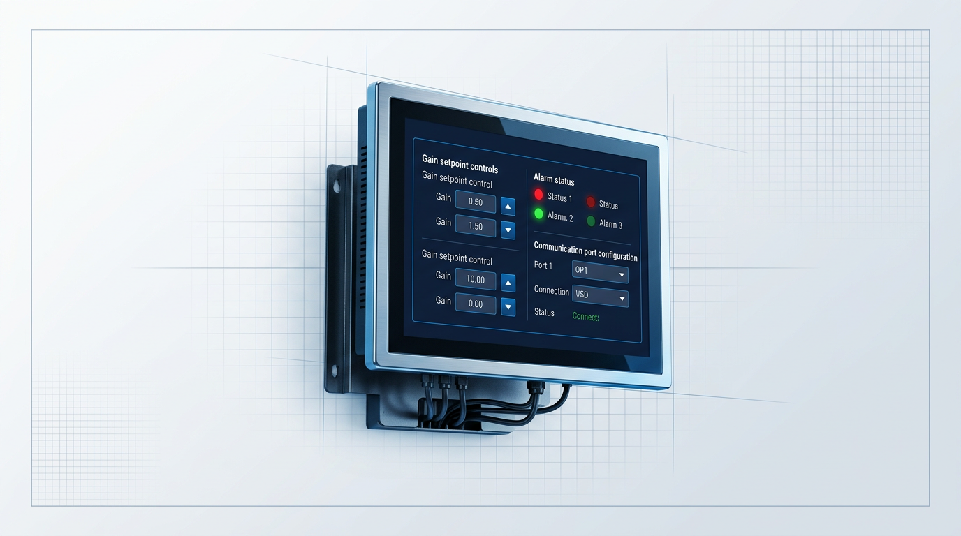
Control Firmware and Comms Specified Per Project
Gain control mode, alarm outputs, and remote monitoring interfaces are part of the configuration. Firmware and communication standards are engineered to the integration requirement.

Designed, Built, and Supported In-House in Southampton
CE and UKCA certified. Designed, built, and supported in-house in Southampton, UK — with direct engineering support from the team who built the unit.
Custom-Engineered vs Catalogue: When It Matters
For low-demand links, a fixed module is often adequate. For anything more — unusual band, tight margin, demanding form factor, or integration that needs real engineering support — the build approach has direct system-level consequences.
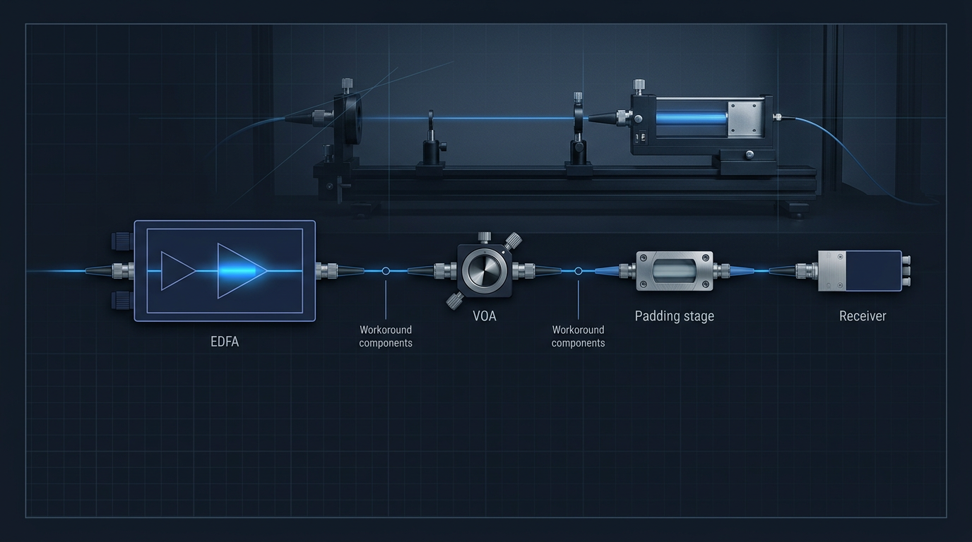
Fixed Modules Force Costly System Workarounds
Each workaround — padding, VOAs, extra stages — costs OSNR and erodes system margin.
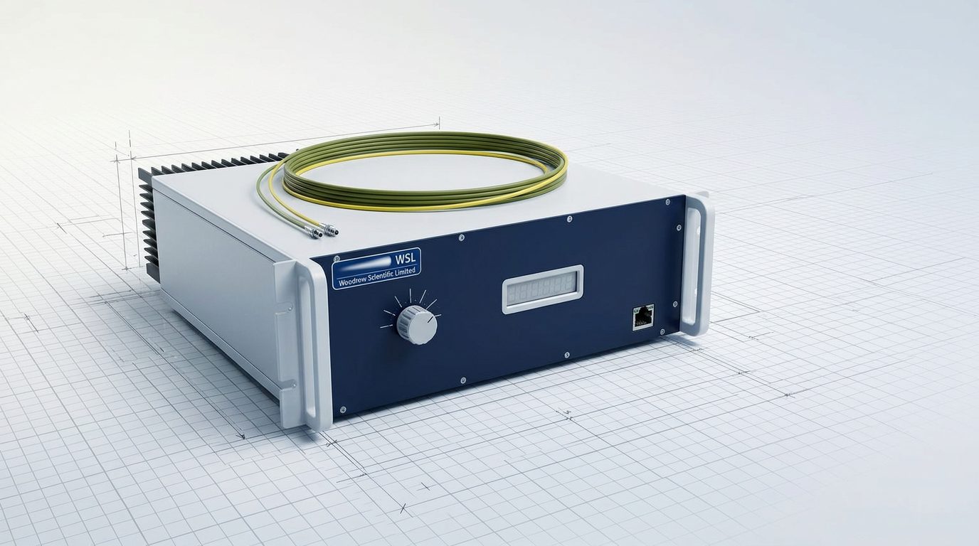
Every Parameter Configured to the Application
A unit built to spec avoids the compromises a fixed module forces on the system.

Manufacturer, Not Reseller or Importer
Resellers carry no in-house engineering: integration issues resolve slower and the product cannot adapt.
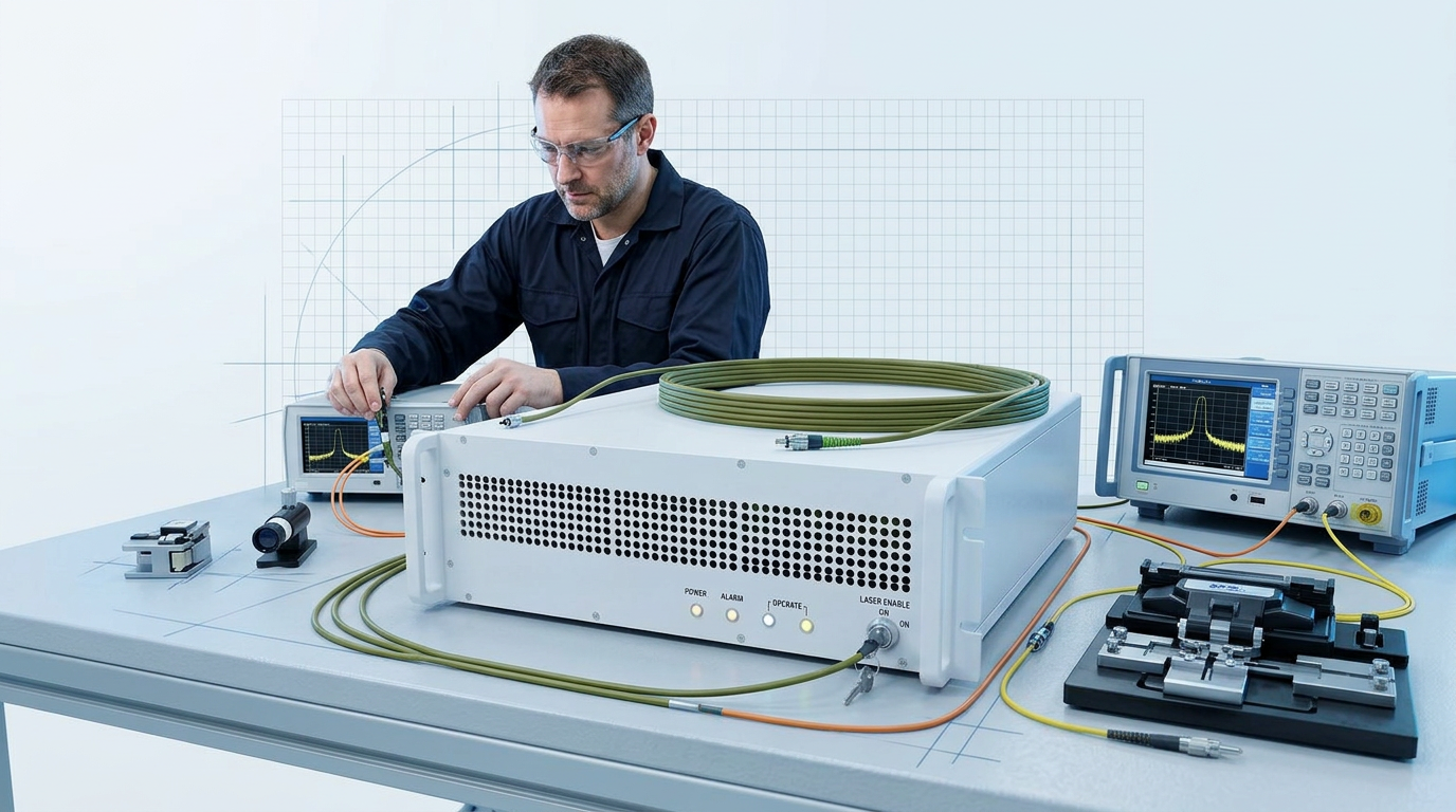
Engineering Support Throughout Integration
WSL's support runs from specification to deployment — not just a datasheet and a warranty.
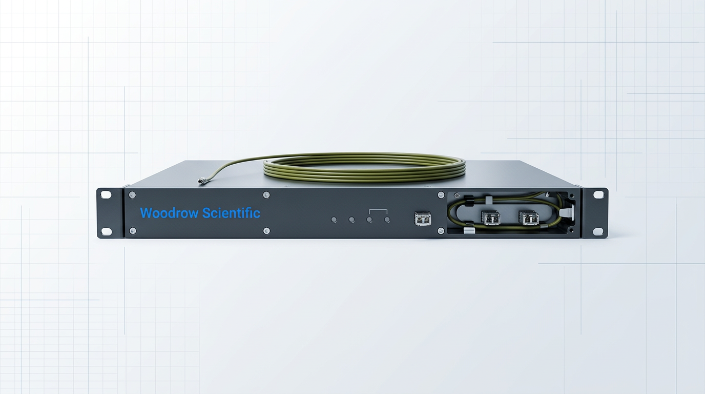
When a Catalogue Unit Is the Right Call
Low channel count, standard span loss, no unusual form factor or control needs: catalogue fits.

Requirements Beyond Spec Assessed With Your Engineers
WSL builds to order: no requirement is ruled out before the engineering conversation.
Custom EDFAs Built to Your Specification
WSL engineers custom EDFAs to the parameters your DWDM link demands. No requirement is ruled out before the engineering conversation — bring your specification and we will build to it.

EDFA DWDM Applications Across Industries and Disciplines
The 1530–1625 nm erbium window is the established amplification platform well beyond carrier telecom. Data centre interconnect links use DWDM in the C-band for DCI-Edge and DCI-Metro deployments, with distinct latency and channel-density requirements. The same platform serves defence and directed-energy research, distributed acoustic and structural fibre sensing, free-space optical communications — including ground-station uplink builds such as the EDF-UL-10 — and scientific instrumentation where catalogue parts cannot meet the specification.
Each application demands a different configuration. Band, output power, pulse regime, form factor, and firmware are engineered per project, so the platform serves every discipline without compromise.

Start Your Specification with Application Parameters
Bring your operating band, required output power, link placement role, channel count and spacing, form factor constraints, cooling preference, and control or comms requirements. Each parameter becomes a design input — the unit is built to your specification, not selected from a fixed menu.
WSL's engineers assess every requirement directly with your team. Requirements that sit at or beyond standard parameters are not ruled out in advance — they are evaluated on their merits. Quotations are configured to the application. Engineering support continues from specification through to deployment, and orders are fulfilled worldwide direct from WSL.
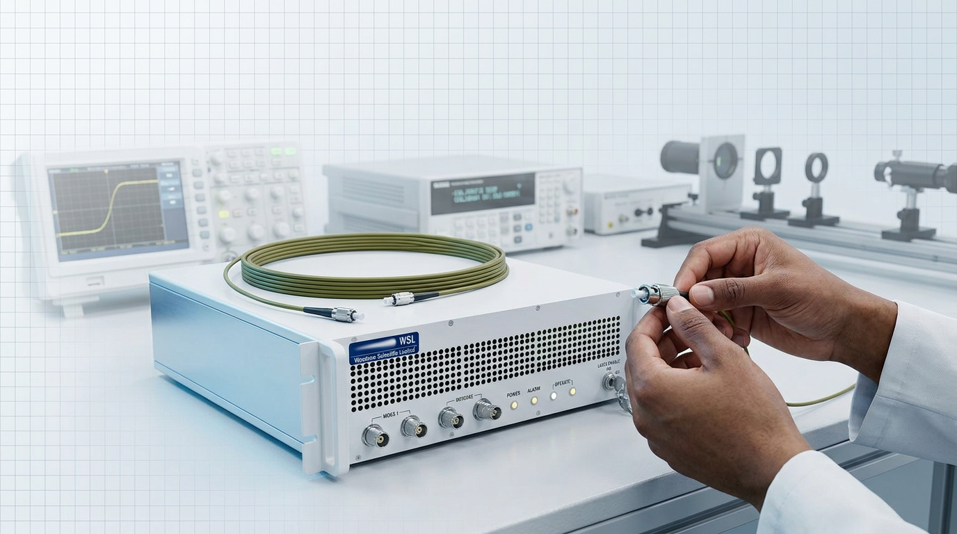
EDFA for DWDM: Frequently Asked Questions
Technical specification and product questions on EDFA amplifiers for DWDM systems, answered directly.
The core parameters are: operating band (C-band, L-band, or dual C+L), output power, noise figure, gain flatness across the channel plan, gain control mode (constant gain or constant output power), form factor, cooling preference, and control/communications interface. The Cisco DWDM planning guide identifies gain, gain flatness, noise level, and output power as the key performance parameters of optical amplifiers, with low noise and flat gain as the primary selection targets. Link placement sharpens which of these to weight most heavily. A booster position prioritises saturated output power above all else; an inline position demands tight control of both noise figure and gain flatness because ASE accumulates across every cascaded stage; a pre-amplifier position puts noise figure first, since its contribution directly determines receiver sensitivity. Confirm placement before finalising the specification.
The three roles differ by position in the link and by which performance parameter matters most. A booster amplifier sits directly after the transmitter and prioritises high saturated output power to launch into the first span; ITU-T G.663 defines it as a high saturation-power device that does not need stringent noise requirements. An inline (line) amplifier sits between fibre spans and must control both noise figure and gain flatness tightly, because ASE noise accumulates additively across every cascaded stage. A pre-amplifier sits immediately before the receiver to improve its sensitivity; ITU-T G.663 defines it as a very low noise device, making minimum noise figure the governing specification for that role. Two-stage designs with mid-stage access allow dispersion compensation modules or OADMs to be inserted between gain stages without degrading the overall noise figure — a practical consideration for long-haul and reconfigurable links.
A fixed catalogue module is a compromise whenever the application has specific band, output power, form factor, cooling, or control requirements. A purpose-built unit is configured to the system from the outset, avoiding the workarounds — padding stages, variable optical attenuators, additional gain stages — that a mismatched module forces on the design and that each cost OSNR and erode system margin. WSL's Custom EDFA is engineered end-to-end to the application: operating band (C-band, L-band, or dual C+L), output power, pulse regime, cooling, form factor, delivery cable, and control firmware are all specified per project. Because WSL designs, builds, qualifies, and supports its amplifiers in-house in Southampton — on patented technology, backed by more than 200 years of combined engineering experience — the tailoring process is seamless and support after delivery is direct from the engineers who built the unit. Many suppliers in this market are resellers rather than manufacturers, which limits their ability to adapt a product or resolve integration issues at depth. A purpose-built unit from a manufacturer eliminates that gap.
Yes. WSL ships worldwide, direct from Southampton. Buyers in any country order direct with WSL regardless of geography — there is no regional distributor or intermediary required. WSL's Custom EDFA is CE and UKCA certified, and the same direct engineering support that UK customers receive is available to international buyers throughout specification and integration.
An EDFA (erbium-doped fibre amplifier) amplifies all DWDM wavelengths simultaneously in the optical domain, without optical-to-electrical-to-optical (OEO) conversion, compensating for fibre span loss across the full channel comb. As the Cisco DWDM planning guide notes, optical amplifiers boost all wavelengths at once without electrical conversion — making the EDFA the enabling technology for long-distance multi-wavelength transmission. EDFA gain covers the 1530–1625 nm window, spanning the C-band (1530–1565 nm) and L-band (1565–1625 nm). A single amplifier can therefore serve all channels on the ITU-T frequency grid simultaneously in one pass. This property — that the amplifier count does not scale with channel count — is why EDFAs replaced optoelectronic repeaters for DWDM links. Each repeater in the older architecture required a separate OEO conversion per wavelength; a single EDFA handles the entire channel comb together.
An EDFA is an all-optical amplifier that uses erbium-doped fibre pumped at 980 nm or 1480 nm to provide gain across the 1530–1625 nm window. It amplifies signals entirely in the optical domain, without converting them to electrical form at each amplification point. As IEEE TechNav describes, the pump laser excites erbium ions to a higher energy state; incoming signal photons then stimulate those ions to emit coherent photons at the same wavelength, producing optical gain through stimulated emission. This mechanism replaced optoelectronic repeaters in long-haul fibre networks, enabling modern high-capacity transmission at scale. The practical significance for DWDM systems is direct: because the EDFA amplifies in the optical domain, it serves all wavelengths present in its gain window simultaneously in a single pass. That makes it the foundational component of any multi-channel fibre link — one amplifier, many wavelengths, no per-channel conversion overhead.