

Introduction
In a conventional satellite network, data moving between two spacecraft takes a detour most people never consider: it descends to the ground, passes through terrestrial infrastructure, and climbs back up — adding latency, creating coverage gaps, and tying performance to wherever ground stations happen to exist.
The ability for satellites to communicate directly with each other changes that constraint in ways that matter deeply to how modern constellations are designed.
This guide is written for engineers, constellation operators, and procurement leads who want precision and depth — not an introductory overview.
It connects three layers most resources treat separately: the underlying technology, real-world deployment challenges, and the regulatory landscape that shapes what is actually buildable and licensable — moving from foundational concepts through architecture, applications, and evolving standards.
TL;DR
The satellite industry is converging on optical ISLs as the technology of choice for high-capacity, ground-independent connectivity — but the technology alone is only part of the picture.
Practitioners who grasp the full scope — from link physics and pointing tolerances to spectrum governance and a standards landscape still maturing — are positioned to design systems that stay adaptable.
This article covers:

How RF and optical ISL technologies work
Pointing, acquisition, and tracking for optical ISLs
ISL network architecture and topology options
Deployment challenges: latency, protocols, and ground stations
Applications: mega-constellations, Earth observation, small satellites
Regulatory and spectrum management for ISLs
What is an intersatellite link?
At its core, an intersatellite link (ISL) is a direct communications link between two artificial satellites in orbit — one that carries signals from spacecraft to spacecraft without routing through a ground station at any point in between.
Three elements of that definition matter. The link is satellite-to-satellite: no terrestrial node sits in the signal path. It operates entirely in orbit: both endpoints are spacecraft. And it bypasses ground infrastructure: the signal never descends to Earth to be forwarded onward.
The same concept appears under different names depending on context. Engineers and operators commonly call it a crosslink; the ITU's regulatory framework classifies it under the inter-satellite service (ISS). All three terms — intersatellite link, crosslink, and ISS link — refer to the same fundamental architecture and will appear interchangeably throughout this guide.
The problem ISLs solve
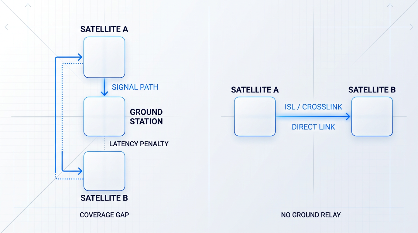
Without ISLs, passing data between two satellites requires a full bent-pipe relay: the first satellite downlinks to a ground station, the ground station uplinks to the second satellite, and only then does the data arrive at its destination.
This architecture has three concrete costs. It adds latency at every ground hop. It creates coverage gaps wherever ground infrastructure does not exist — polar regions, open ocean, and remote land masses are structurally underserved. And it ties network performance to the physical placement of ground facilities, which are expensive, politically negotiated, and geographically fixed.
Removing the ground station from the signal path is not an optimisation — it is a structural change to the network's architecture, and it is the defining characteristic that separates an ISL from conventional satellite relaying.
Historical roots and classification by orbital geometry
The relay problem that ISLs address was identified almost as soon as the satellite era began: Clarke's 1945 paper on geostationary communication satellites implicitly framed the need for spacecraft-to-spacecraft relay to achieve truly global, ground-independent coverage.
NASA literature from the 1980s formalised a classification framework that remains a useful mental model today. The 1987 NASA NTRS study identifies four generic ISL categories, defined by the orbital separation between the linked satellites.
- Intercluster links: Satellites separated by less than 0.1°, operating in very close proximity within the same orbital slot or cluster.
- Intra-plane links: Links between satellites in the same orbital plane, where relative geometry is stable and predictable throughout the orbit.
- Inter-plane links: Links between satellites in adjacent orbital planes, where relative geometry changes continuously and grows complex at high latitudes.
- Global coverage configurations: Links spanning very large angular separations, used to close connections across widely separated parts of a constellation.
The intra-plane versus inter-plane distinction is particularly important in practice. Satellites sharing an orbital plane move together, so their relative positions are geometrically stable — the link geometry is predictable and relatively simple to maintain. Satellites in adjacent planes, by contrast, have continuously shifting relative geometry, and this complexity intensifies at high latitudes where orbital planes converge.
Two technology families
ISL signals are carried by one of two technology families: radio frequency (RF) and free-space optical (FSO) — the latter also referred to as laser ISLs or optical ISLs.
Each family operates on distinct physical principles, offers different operational characteristics, and involves different trade-off profiles in terms of bandwidth, mass, power, and pointing precision. The following sections examine both in depth: §4 covers RF ISLs and §5 covers optical ISLs.
Scope of applications and guide boundaries
ISLs are in use across a wide range of mission types — from legacy geostationary data relay satellites to large LEO mega-constellations to experimental CubeSat demonstrations — and the technology continues to mature rapidly across all of these domains.
This guide covers satellite-to-satellite links throughout. Ground-to-satellite optical links, such as those used by optical ground stations, are a related but distinct topic and appear here only where directly relevant to the architecture of ISL-equipped systems.
With the concept, terminology, and classification established, the next section examines how radio frequency ISLs implement this direct link in practice — covering the heritage systems, frequency choices, and engineering trade-offs that define the RF approach.
RF Intersatellite Links: Bands, Capabilities, and Limits
Radio frequency ISLs have underpinned satellite data relay for decades, carrying mission-critical traffic across some of the most demanding links ever engineered in orbit. Understanding where they perform well — and precisely where they hit a ceiling — is the essential baseline for evaluating any modern intersatellite link architecture.
The operating principle is straightforward: modulated radio waves are transmitted between directional antennas on two satellites, propagating through the vacuum of space with no atmospheric absorption to contend with. Both satellites must point their antennas at each other, and the link operates within spectrum bands allocated by the ITU specifically for the inter-satellite service (ISS) — a dedicated allocation that keeps ISL traffic separate from Earth-space links.
Frequency bands: Ka, V, and Q
Frequency choice is the single most consequential design decision in an RF ISL. It determines how much bandwidth is available, how severe the free-space path loss will be at a given range, how large the antenna apertures need to be to achieve adequate gain, and how mature the available hardware is — all of which feed directly into the spacecraft mass and power budget.
| Band | ITU ISS Allocation | Nominal Bandwidth | Free-Space Loss | Hardware Heritage |
|---|---|---|---|---|
| Ka-band | 22.55–23.55 GHz (forward); 25.25–27.5 GHz (return) | ~2.25 GHz combined | Lower relative to V/Q at ISL distances | Mature; extensive operational heritage (TDRS, EDRS-A) |
| Q-band | 32.0–33.0 GHz | ~1 GHz | Moderate; higher than Ka-band | Limited; fewer operational deployments |
| V-band | 59.3–71.0 GHz | ~11.7 GHz | Higher than Ka/Q at equivalent range | Emerging; demonstrated at breadboard level (ESA Gigabaud) |
Comparison of the three primary RF ISL frequency bands across ITU allocation, bandwidth, free-space loss characteristic, and hardware heritage — enabling engineers and procurement leads to evaluate band trade-offs at a glance.
Ka-band's dominance in heritage systems reflects a practical balance: the combined ISS allocations offer usable bandwidth, free-space loss remains manageable at typical ISL distances, and decades of flight-proven hardware reduce programme risk significantly.
V-band's appeal is its much wider allocation — nearly 11.7 GHz of ISS spectrum compared with Ka-band's roughly 2.25 GHz — but that headroom comes at a cost: higher free-space path loss at equivalent ranges demands either larger antenna apertures or greater transmit power, both of which carry spacecraft resource implications. Hardware at V-band frequencies is also less mature, making it a higher-risk choice for operational missions.
Heritage RF ISL systems
NASA's Tracking and Data Relay Satellite (TDRS) system is the canonical reference point for operational Ka-band ISLs. The Ka-band single access service uses the 22.55–23.55 GHz forward allocation and the 25.25–27.5 GHz return allocation, supporting return service data rates of up to 300 Mbps on 225 MHz channels and up to 800 Mbps on 650 MHz channels using QPSK modulation.
EDRS-A, the first payload of ESA's European Data Relay Satellite system, demonstrates a different approach: it combines an optical ISL terminal with a Ka-band ISL terminal on the same platform, with the Ka-band link supporting data rates of up to 300 Mbps. This hybrid RF and optical architecture gives the system flexibility to serve user spacecraft with different terminal capabilities, and it positions the Ka-band link as both a primary relay path and a fallback alongside the optical channel.
The upper end of demonstrated RF ISL throughput comes from ESA's Gigabaud project, a wideband modem breadboard that exploits the 59–71 GHz V-band ISS allocation using CCSDS 131.2-B-2 coding and modulation. The breadboard achieved data rates beyond 1 Gbps at signal-to-noise ratios below 0.7 dB, including under Doppler scenarios representative of large LEO constellations — a result that shows how far RF ISL technology can be pushed when the full V-band allocation is exploited.
Link budget constraints and the data-rate ceiling
Every RF ISL is governed by a link budget: an accounting of the signal power available at the receiver after all gains and losses are applied. The key parameters are EIRP (effective isotropic radiated power, the product of transmit power and antenna gain), free-space path loss (which scales with both distance and frequency), receive antenna gain, and system noise temperature. Closing the link at a target data rate requires the received signal to exceed the noise floor by a sufficient margin — and at ISL distances of hundreds to tens of thousands of kilometres, the free-space loss is enormous.
The practical consequence is that achieving high data rates at ISL distances requires either very large antenna apertures (to increase gain on both transmit and receive), very high transmit power, or both — all of which translate directly into spacecraft mass, volume, and power consumption. This is not a solvable problem through clever engineering; it is a fundamental consequence of the physics of radio wave propagation.
These constraints give RF ISLs a set of well-defined limitations that any operator evaluating an intersatellite link architecture must understand clearly.
- Spectrum congestion and ITU licensing: RF ISL operators must register and coordinate frequency assignments through the ITU Radiocommunication Bureau; ISS bands are shared and coordination adds deployment complexity.
- Bandwidth ceiling: Even the widest ISS allocation (V-band at ~11.7 GHz) is measured in gigahertz — orders of magnitude below the terahertz-scale bandwidth available at optical frequencies.
- Antenna aperture and mass: High data rates at ISL distances demand large apertures on both spacecraft, increasing mass, volume, and structural complexity — a constraint that worsens as throughput requirements grow.
- Interference susceptibility: RF beams spread broadly compared with laser links, making RF ISLs more vulnerable to interference from adjacent or co-allocated systems sharing the same bands.
For a constellation operator weighing RF against optical ISLs, these limitations are not abstract: they translate into tangible programme constraints. Spectrum coordination timelines can extend mission planning horizons; the bandwidth ceiling caps the throughput available to high-revisit Earth observation missions; and the antenna mass penalty compounds across a large constellation where every kilogram of payload has a cost.
ESA's Gigabaud project — the most advanced demonstrated RF ISL modem — achieved data rates beyond 1 Gbps using the full V-band allocation. EDRS-A's optical terminal operates at up to 1.8 Gbps routinely. That gap, between the best RF demonstration and a fielded optical system, illustrates why the two technologies occupy different parts of the design space rather than competing directly.
Where RF ISLs remain the right choice
RF ISLs are not being displaced across the board — they remain the appropriate technology for a well-defined set of use cases. Lower-data-rate relay links, where the bandwidth ceiling is not a binding constraint, are a natural fit: command uplink, telemetry, and low-rate science data do not require gigabit throughput, and RF provides a simpler, more heritage-proven solution for these roles.
In hybrid architectures such as EDRS-A, the Ka-band ISL terminal serves as both an alternative relay path for spacecraft that lack optical terminals and a redundancy layer alongside the optical link — a role that will remain relevant as optical ISL adoption grows but does not yet reach every platform. Similarly, heritage missions with existing RF infrastructure have no compelling reason to retrofit optical capability when the data rate requirement is already met.
There is also a systems engineering argument for RF on platforms where the pointing, acquisition, and tracking demands of optical ISLs are not justified by the data rate requirement — the precision required to lock two laser terminals across thousands of kilometres introduces engineering complexity that RF's comparatively forgiving beamwidths avoid entirely.
These constraints — spectrum scarcity, the bandwidth ceiling, and the antenna aperture demands at high data rates — are what drove the field toward free-space optical ISLs, which approach the problem from an entirely different physical basis.
Optical Intersatellite Links: How Free-Space Laser Communication Works
Where RF ISLs modulate radio waves, optical intersatellite links carry data on something fundamentally different: a coherent laser beam at near-infrared frequencies, propagating through the vacuum of space between two satellites separated by hundreds or thousands of kilometres.
The physical property that sets optical apart from RF is beam divergence. A beam's divergence angle is proportional to wavelength divided by aperture diameter (θ ≈ λ/d). Because optical wavelengths sit in the micrometre range — roughly 10,000 times shorter than Ka-band RF — an optical terminal with a 10 cm aperture produces a beam that diverges at only a few microradians, compared to the far wider spread of an RF antenna of comparable size.
That narrow divergence concentrates transmitted energy onto an extraordinarily small area at the receiver, delivering far higher received power per unit aperture than any RF system can achieve at the same transmitted power — and it is this concentration that is the root physical cause of the data-rate advantage.
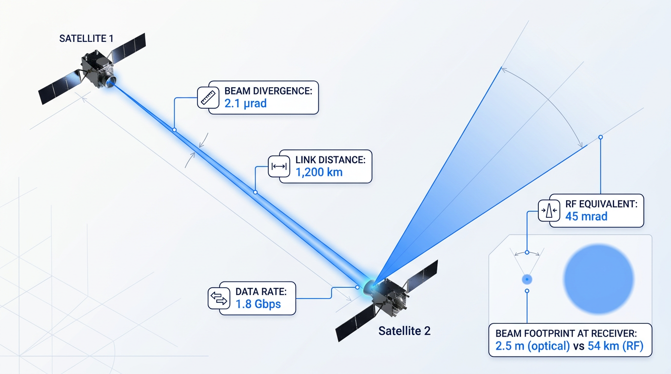
Critically, the propagation medium for a satellite-to-satellite optical link is near-perfect vacuum: no atmospheric turbulence to distort the wavefront, no cloud cover to block the path, no molecular absorption bands to attenuate the signal.
This distinguishes optical ISLs sharply from space-to-ground optical links, which must fight all of those atmospheric effects on every pass. In the space-to-space case, the propagation physics are clean and predictable; the engineering challenge shifts entirely to keeping the beam on target — a problem known as pointing, acquisition, and tracking (PAT), which the next section addresses in full.
Wavelength Selection: Why 1550 nm Dominates
Operational optical ISLs converge on 1550 nm — the C-band of the near-infrared — and the choice is not arbitrary. It is the wavelength at which erbium-doped fibre amplifiers (EDFAs) provide gain, and EDFAs represent one of the most mature, high-performance amplification technologies in photonics, developed over decades for the global terrestrial fibre-optic telecommunications industry.
By designing around 1550 nm, optical ISL engineers gain access to an entire commercial ecosystem: high-power EDFA modules, low-noise photodetectors, mature modulators, single-mode fibre, and precision connectors — all developed and refined at enormous scale for terrestrial telecoms, and available at a fraction of the cost of bespoke space components.
A third factor reinforces the choice: 1550 nm has a higher eye-damage threshold than the 1064 nm (Nd:YAG) wavelength used in earlier systems, including the TESAT laser communication terminals (LCTs) on the original EDRS nodes. The 15xx nm band is less readily absorbed by the eye's lens and retina, which matters for ground safety protocols when a satellite beam could theoretically intersect the Earth's surface.
The 1064 nm wavelength remains in use — EDRS Global's upgraded EDRSD payload supports dual-wavelength operation at both 1064 nm and 1550 nm to serve a wider customer base — but for new optical ISL designs, 1550 nm is the established standard, and the EDFA ecosystem is a primary reason why.
The Bandwidth Advantage: Terahertz vs Megahertz
Optical frequencies are roughly five orders of magnitude higher than Ka-band RF. As NASA research has noted, at Ka-band the usable bandwidth is typically around 500 MHz; at 1550 nm, the available bandwidth can be 1,000 times larger — measured in terahertz rather than megahertz.
In practice this translates to demonstrated data rates that dwarf anything achievable with RF ISLs. The EDRS optical terminal — on the same satellite platform as a Ka-band ISL delivering up to 300 Mbps — achieves up to 1.8 Gbps via its TESAT LCT: a 6× improvement from the same orbital slot, over distances up to 45,000 km.
| System | Link Type | Distance | Data Rate |
|---|---|---|---|
| EDRS (TESAT LCT) | GEO-to-LEO | Up to 45,000 km | 1.8 Gbps |
| Amazon Kuiper prototypes | LEO-to-LEO | ~1,000 km (tested); up to 2,600 km (designed) | 100 Gbps (two-way) |
| Telesat Lightspeed (planned) | LEO-to-LEO | Not published | 4 × 10 Gbps per satellite |
| NASA TBIRD (CubeSat) | Space-to-ground (LEO) | LEO orbit | 200 Gbps |
Comparison of demonstrated optical laser communication data rates across operational and prototype systems, to show the real performance envelope of the technology.
The table spans more than two orders of magnitude in data rate, from EDRS's mature 1.8 Gbps operational service to TBIRD's 200 Gbps demonstration — and the top end is not a large, purpose-built research platform but a 6U CubeSat weighing roughly 12 kg.
Amazon's Kuiper prototypes, KuiperSat-1 and KuiperSat-2, sustained a two-way 100 Gbps optical link for around an hour at a time at nearly 1,000 km separation, with the technology designed to operate across distances up to 2,600 km — figures reported by SpaceNews following Amazon's December 2023 announcement.
Telesat Lightspeed's architecture places four 10 Gbps optical ISLs on every satellite — front, back, left, and right — forming a global mesh; this is not an afterthought but a design principle, with the optical links engineered to reach twice the required distance so that one satellite can be skipped entirely if needed.
Advantages Over RF ISLs
The data-rate advantage is the most visible benefit, but four further structural advantages explain why optical ISLs are being designed into next-generation constellations from the outset rather than added as an upgrade.
- No ITU spectrum licensing: Optical frequencies sit above 3000 GHz, outside the ITU Radio Regulations. There is no spectrum coordination, no filing with the ITU Radiocommunication Bureau, and no interference coordination with other operators.
- Lower mass and power (SWaP): NASA analysis found that optical flight terminals exhibit approximately 60% of the mass of comparable RF subsystems at equivalent high data volumes, a direct benefit to constellation economics.
- Inherent security and interference resistance: Microradian-scale beam divergence means the beam illuminates an extremely small area. Interception requires a third party to be physically in the beam path — geometrically very difficult in orbit.
- No RF spectrum congestion: Optical ISLs do not compete for increasingly contested RF allocations. As constellation numbers grow and RF spectrum tightens, this advantage compounds.
The SWaP advantage deserves particular emphasis for constellation operators: at high data rates, the mass saved per satellite compounds across hundreds or thousands of spacecraft, directly reducing launch cost and enabling smaller satellite buses. ESA's assessment for the next-generation Galileo navigation system concluded that optical ISLs are the best technology choice, citing proven maturity through EDRS and the Copernicus Sentinels, alongside the freedom from ITU frequency regulation.
The security property is a physical consequence of the optics, not a design feature that can be switched off: the same microradian divergence that concentrates power at the intended receiver makes the beam nearly impossible to intercept without the interceptor being detectable — a characteristic that RF links, with their far wider beam footprints, fundamentally cannot replicate.
Modulation Approaches: IM/DD and Coherent
Operational optical ISLs use two broad families of modulation. Intensity modulation with direct detection (IM/DD) is the simpler approach: the laser's output power is varied to encode data, and the receiver measures that intensity directly. It requires less signal-processing complexity and lower power consumption, making it well-suited to systems where simplicity and heritage matter — the TESAT LCTs at the heart of EDRS operate on this principle.
Coherent modulation is more demanding: the receiver mixes the incoming optical signal with a local oscillator laser and extracts data from the phase and amplitude of the combined signal. The payoff is substantially better receiver sensitivity and higher spectral efficiency, enabling longer link distances and higher data rates for a given transmitted power. TBIRD's 200 Gbps demonstration used coherent transceivers — specifically dual-polarisation QPSK with dedicated ASICs for digital signal processing and forward error correction — leveraging commercial fibre-telecom components adapted for the space environment.
Space-to-ground optical links must contend with atmospheric turbulence, cloud blockage, and wavelength-dependent absorption on every pass. A satellite-to-satellite optical link faces none of these. The propagation medium is near-perfect vacuum, making the link budget clean and deterministic — and shifting the entire engineering challenge to keeping a microradian-scale beam locked on a moving target across thousands of kilometres.
This vacuum advantage is what makes the demonstrated figures in the table above achievable at all. TBIRD's 200 Gbps is a space-to-ground link and still had to manage atmospheric fading through an ARQ protocol; a pure satellite-to-satellite link at the same wavelength and modulation scheme, operating in vacuum, faces a cleaner and more predictable link budget with no stochastic atmospheric component.
The same narrow beam that delivers these data rates — diverging at only a few microradians across thousands of kilometres — is precisely what makes pointing so demanding: a misalignment of a fraction of a microradian can take the receiver out of the beam entirely. How operational systems solve that problem is the subject of the next section.
Pointing, Acquisition, and Tracking: Optical ISL's Core Challenge
An optical ISL beam diverges on the order of microradians — a cone so narrow that across 45,000 km, even a sub-arcsecond pointing error is enough to miss the target aperture entirely. RF beams at comparable frequencies are orders of magnitude wider, so coarse attitude control suffices to keep the link open; with an optical beam, it does not.
This is why pointing, acquisition, and tracking (PAT) — also referred to in the literature as ATP (acquisition, tracking, pointing) — is the defining engineering challenge for optical ISL terminals. The problem is decomposed into three sequential phases, each solving a different part of the angular uncertainty.
- Acquisition: The coarse search phase. One or both terminals scan a spatial uncertainty region to locate the counterpart before a link can be established.
- Tracking: Once the counterpart is detected, the terminal enters closed-loop tracking, continuously measuring the received beam's angle of arrival and feeding corrections to the pointing hardware.
- Pointing: The fine correction phase: actively steering the transmit beam to keep it centred on the far-end aperture, compensating for jitter, vibration, and relative spacecraft motion.
Knowing the sequence is one thing; implementing it in hardware is another. The dynamic range of the problem — from milliradian-class attitude uncertainty down to sub-microradian pointing stability — is too large for any single actuator to span.
Most optical ISL terminals therefore implement pointing in two stages: a coarse stage and a fine stage working in tandem.
- Coarse pointing: A gimbal rotates the telescope, or spacecraft attitude control reorients the entire bus. Handles large angular excursions but lacks the bandwidth for high-frequency jitter.
- Fine pointing: A fast steering mirror (FSM), driven by piezoelectric or voice-coil actuators, corrects residual jitter at bandwidths from hundreds of Hz to the kHz range.
The two stages are complementary by necessity: the coarse stage alone lacks the precision and bandwidth to maintain a microradian-class beam on target; the fine stage alone lacks the angular range to cover the initial uncertainty. Together they address the full dynamic range of the pointing problem.
For operational terminals, beacon-based acquisition is the dominant approach. One terminal illuminates a wide-angle beacon beam — diverged deliberately to cover the counterpart's spatial uncertainty region — while the counterpart detects the beacon on a wide-field focal plane array (CCD or CMOS) and uses the detected position to close the pointing loop. Once both terminals are mutually tracking each other's beacon, the narrow data beam is activated.
The EDRS laser communication terminals (LCTs), built by TESAT Spacecom, are the operational benchmark for beacon-based acquisition. According to ESA, the terminals take approximately 55 seconds to establish a link from GEO to LEO — locking on to a 135 mm diameter aperture across 45,000 km, with the LEO spacecraft travelling at 8 km/s relative to Earth.
Where a beacon is unavailable or impractical — such as deep-space links, or platforms where the mass and power of a beacon transmitter cannot be justified — beaconless acquisition is the alternative. These systems rely on high-accuracy star trackers to establish precise inertial orientation, inertial measurement units (IMUs) or gyroscopes to propagate that knowledge between star tracker updates, and precise ephemeris data for the counterpart to predict where to point.
Analysis by JPL and MIT Lincoln Laboratory has shown that a star-tracker-based ATP system, using an 8 cm telescope aperture with commercially available star trackers and inertial sensors, can achieve pointing knowledge of approximately 150 nanoradians (single axis, 1-sigma) — well below the 200–300 nanoradian tolerance typical of deep-space optical communications requirements.
The microradian divergence that gives optical ISLs their capacity advantage over RF is the same property that makes sub-microradian pointing accuracy non-negotiable. There is no way to have one without the other — PAT is not an add-on; it is structurally inseparable from the optical ISL design.
The quantitative requirement follows directly from link budget physics: to keep mispoint losses below 2 dB, the JPL Descanso monograph establishes that total pointing accuracy must be held to less than 40% of the diffraction-limited beamwidth — which for deep-space optical links translates to a total error budget on the order of 1 microradian.
On-orbit results from NASA's TBIRD (TeraByte InfraRed Delivery) mission — a 3U lasercom payload on a 6U CubeSat that demonstrated 200 Gbps optical downlinks from LEO — show what is achievable in practice. Riesing et al. (SPIE 2023) report closed-loop tracking performance of 20–35 µrad RMS per axis, with typical pointing losses below 0.1 dB against a 380 µrad FWHM transmit beam.
The PAT challenge scales differently on small satellite platforms. On a CubeSat, body-pointing alone — reorienting the entire spacecraft to aim the optical terminal — is insufficient for narrow optical beams: it is too slow and too imprecise to maintain link margin.
MEMS fast steering mirrors are the enabling hardware for fine pointing on small platforms, offering the compact form factor, low power draw, and high actuator bandwidth that CubeSat mass and volume budgets demand. The CLICK-A (CubeSat Laser Infrared CrosslinK) mission demonstrated this architecture on a 3U CubeSat: the payload's MEMS FSM provided fine pointing of its 1,300 µrad FWHM downlink beam, serving as a risk-reduction precursor to the CLICK-B/C crosslink demonstration.
With the PAT challenge understood at the terminal level, the natural next question is how those terminals are organised within a constellation — what topology they form, how data is routed between nodes, and how the ground segment integrates with the on-orbit network.
ISL Network Architecture: Topology, Routing, and Ground Integration
Establishing a stable optical or RF link between two satellites is an engineering achievement in itself — but a single link is not a network. The harder architectural question is how to organise hundreds of satellites, each capable of communicating with its neighbours, into a coherent system that can route a packet reliably from any point in orbit to any point on Earth, without waiting for a ground station to pass into view.
Network Topology Options: Ring, Mesh, and Relay
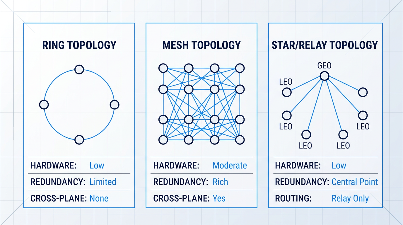
Three fundamental ISL topology patterns define how satellite networks are structured: ring, mesh, and star/relay. Each represents a different answer to the trade-off between hardware complexity, path redundancy, and coverage continuity.
- Ring topology: Each satellite connects to its two immediate neighbours within the same orbital plane. Simple and low in hardware count, but offers no cross-plane connectivity and limited redundancy if a link fails.
- Mesh topology: Satellites connect to neighbours in adjacent orbital planes as well as within their own plane — typically two intra-plane and two inter-plane ISLs per satellite. Richer redundancy and more routing paths, at the cost of more terminals and more complex geometry.
- Star / relay topology: A central relay satellite — typically in GEO — connects to multiple user satellites beneath it. Well-suited to data relay architectures; not practical for LEO mega-constellations requiring peer-to-peer routing.
For LEO mega-constellations, the mesh topology is the dominant architectural choice: the additional inter-plane links are what enable true multi-hop routing across the constellation, rather than confining data flow to a single orbital plane.
The star/relay pattern, by contrast, suits systems like EDRS, where GEO relay nodes act as persistent intermediaries between LEO satellites and ground stations — a fundamentally different architectural logic than a peer-routed LEO network.
Intra-Plane and Inter-Plane Links: Geometry and Stability
Intra-plane ISLs connect satellites within the same orbital plane. Because both satellites share the same orbit, their relative geometry is stable and predictable: link distance and pointing angles change slowly and smoothly across the orbital period, making these links comparatively straightforward to maintain.
Inter-plane ISLs connect satellites in adjacent orbital planes, where the geometry is considerably more demanding. The two planes are inclined relative to each other, so the relative motion between satellites is non-uniform — the angular rate and link distance vary continuously, and the pointing solution must track a more complex trajectory.
This geometric distinction has a practical architectural consequence: research into heterogeneous ISL topologies has proposed exploiting it deliberately, using stable high-throughput laser links for intra-plane connections and more flexible radio links for inter-plane connections, where the dynamic geometry suits RF's faster acquisition capability.
The geometric challenge intensifies at high latitudes. As satellites in a Walker-Delta constellation approach the poles, adjacent orbital planes converge — satellites in neighbouring planes draw physically closer together, and the relative angular rate between them rises sharply.
The engineering consequence is that inter-plane ISL geometries near the poles become impractical to maintain: the terminal cannot track the rapidly changing pointing angle, and the link distance varies too dramatically to sustain a stable connection.
The standard architectural response is polar pruning — simply not activating inter-plane ISLs at high latitudes. Starlink's operational topology applies this approach: inter-plane links are pruned near the poles, leaving only intra-plane links active in those regions.
Pruning inter-plane ISLs at high latitudes increases worst-case path distance and end-to-end delay compared to a hypothetical full-mesh — but it remains substantially preferable to operating with no inter-plane links at all. Every real LEO mesh constellation must account for this geometric constraint in its topology design.
On-Board Routing: Satellites as Routers, Not Repeaters
A mesh-connected constellation only functions as a network if each satellite can make intelligent forwarding decisions — determining which ISL hop a packet should take next toward its destination. This requires on-board processing capability and routing tables, not just signal relay.
In terrestrial networks, distributed routing protocols dynamically discover topology and recompute routes as the network changes. For a single-operator LEO constellation, a more practical alternative exists: because orbital mechanics are precisely known in advance, the constellation's topology at any future moment can be pre-computed on the ground and uploaded to satellites as time-indexed routing snapshots.
This centralised pre-computation approach reduces on-board computational demands and avoids the convergence delays that distributed protocols introduce — a meaningful advantage when a satellite's entire contact window with a ground station may last only a few minutes. The specific routing protocols that implement this logic are an active area of standardisation, covered in later sections.
Ground Segment Integration: Fewer Stations, Higher Capacity
Without ISLs, every satellite must be within direct line-of-sight of a ground station to deliver its data — a satellite over the central Pacific or the Arctic must simply wait until its orbit brings it over a receiving facility. ISLs break this dependency: a satellite with no ground contact can relay its data hop-by-hop through the constellation until it reaches a satellite that is in contact with a ground station.
This changes the ground segment calculus fundamentally. As Caleb Henry of Quilty Analytics has noted, data relay systems should reduce the need for site diversity — though they will not eliminate the need for ground stations altogether, since data that needs to reach Earth must still cross the space-to-ground boundary.
The architectural shift is one of consolidation rather than elimination: ISLs allow gateway sites to be concentrated at fewer, higher-capacity locations with good fibre backhaul, rather than distributed across remote or polar sites chosen purely to maximise contact frequency with individual satellites.
A concrete illustration: without ISLs, a satellite over Antarctica can only downlink when it passes over a ground station, forcing operators to maintain remote polar facilities with limited backhaul. With ISLs, that satellite can route its data through the constellation to a satellite over Australia, where fibre connections are plentiful — the remote station becomes architecturally optional.
The downlink bottleneck does not disappear, however. Even with ISLs consolidating traffic across the space segment, the pipe between each ground station and the satellite overhead remains capacity-limited — and rising data volumes mean that fewer but higher-capacity ground stations must each handle a larger share of total throughput.
This is why the ground segment is a first-class architectural concern in any ISL-equipped constellation design, not an afterthought. The number of ground stations, their geographic placement, and their individual capacity must be sized against the consolidated traffic load that ISL routing will deliver to them.
Some operational systems resolve this with a hybrid RF and optical architecture: optical ISLs carry high-throughput traffic between satellites in the space segment, while RF links handle the final downlink to the ground. EDRS exemplifies this pattern — laser communication terminals deliver up to 1.8 Gbps between satellites, while Ka-band RF links carry data to ground stations and provide a lower-speed redundancy layer.
ESA's Data Relay Constellation (DRC) follows the same hybrid logic, combining optical inter-satellite links at 2.5 Gbps or higher with S-band and K-band RF links for the ground segment, supported by a global network of strategically placed optical and RF ground stations coordinated through a centralised Mission Control Centre.
The rationale is straightforward: optical links are well-suited to the vacuum of the space segment, where atmospheric interference is absent, while RF links for the ground downlink provide robustness against the cloud cover and atmospheric distortion that can disrupt optical signals on the path to Earth.
With the architectural picture established — topology choices, link geometry constraints, on-board routing logic, and ground segment integration — the next section examines the concrete deployment challenges that arise when these designs move from the drawing board into operational constellations.
Latency, Ground Stations, and Protocol Coordination
Designing an ISL-equipped constellation on paper and operating one in orbit are two very different engineering problems. The latency physics, the persistent ground segment requirement, and the complexity of routing across a continuously shifting topology each present challenges that only become visible once the system is live.
The core of the latency argument is a physical fact: light travels at approximately 299,792 km/s in vacuum but only around 204,288 km/s through silica optical fibre — roughly 47% slower, due to the refractive index of glass.
For short distances this difference is negligible, but on intercontinental routes it accumulates into measurable, operationally significant delays. A LEO ISL constellation routes data through vacuum rather than along submarine fibre cables, and that physical difference translates directly into lower latency on long-haul paths.
| Link / Route | One-way or Round-trip | Latency | Notes |
|---|---|---|---|
| GEO satellite (any route) | Round-trip | 500–600 ms | Altitude ~35,786 km; delay dominated by propagation to/from geostationary orbit |
| LEO ISL constellation (any route) | Round-trip | 20–50 ms | Comparable to terrestrial broadband; altitude ~550–1,200 km |
| New York – Dublin (terrestrial fibre) | One-way | ~25 ms | Shortest fibre/submarine path |
| New York – Dublin (LEO ISL at 550 km) | One-way | ~20 ms | ~5 ms improvement over fibre (19.9%) |
| São Paulo – London (terrestrial fibre) | One-way | ~47 ms | Shortest fibre/submarine path |
| São Paulo – London (LEO ISL at 550 km) | One-way | ~37 ms | ~10 ms improvement over fibre (21.3%) |
| Toronto – Sydney (terrestrial fibre) | One-way | ~76 ms | Shortest fibre/submarine path |
| Toronto – Sydney (LEO ISL at 550 km) | One-way | ~58 ms | ~18 ms improvement over fibre (23.5%) |
Comparison of propagation latency across GEO satellite, LEO ISL constellation, and terrestrial fibre on representative long-distance routes.
The table reveals two important patterns. First, the LEO ISL advantage over fibre is real but route-dependent: longer intercontinental paths yield larger absolute improvements, because the vacuum propagation advantage accumulates over greater distances. Second, the contrast with GEO is stark — a GEO round-trip of 500–600 ms is simply incompatible with latency-sensitive applications such as financial trading or interactive real-time communications, whereas LEO ISL round-trips of 20–50 ms sit comfortably within the envelope those applications require.
It is also worth noting what ISLs do not change: ground stations remain a first-class engineering requirement. As long as data must reach Earth, a ground downlink is unavoidable. What ISLs restructure is the architecture — traffic is consolidated across the space network so that fewer, more strategically placed stations can serve the entire constellation, rather than requiring a ground station within line-of-sight of every satellite at every moment.
As RBC Signals co-founder Christopher Richins has noted, satellites communicating through ISLs is productive only insofar as decisions and data ultimately need to reach the ground — and that requirement does not disappear. Ground network architectures change; they do not go away.
Protocol Coordination Across ISL Hops
The deeper operational challenge is not latency physics but protocol coordination: how does a constellation route data reliably across a network whose topology changes continuously as satellites move through orbit?
Terrestrial IP routing protocols such as BGP and OSPF are designed for networks with stable topologies, where adjacency relationships between routers persist indefinitely. A LEO constellation invalidates that assumption entirely — inter-plane ISL links, particularly in polar regions, connect and disconnect on timescales of minutes as satellites overtake one another.
The saving grace is that LEO orbital mechanics are deterministic and predictable. Because satellite positions at any future time can be computed from known orbital parameters, the full schedule of link availability — which satellites will be in contact with which, and for how long — can be pre-computed on the ground and distributed to every node in the constellation. This pre-computed contact schedule is the foundation on which ISL routing is built.
Contact Graph Routing (CGR) exploits this predictability directly. Rather than discovering routes through dialogue between nodes (impractical over space links), CGR constructs a time-varying model of network connectivity from the contact schedule and computes efficient routes for each data bundle using that graph. Routes are calculated individually per bundle based on priority, expiration time, and current link queue states — there are no static routing tables.
ESA's RouteLEO project, currently in its technology development phase, targets precisely this problem: designing and prototyping a routing solution for LEO constellations that must support safety-critical services — specifically Air Traffic Management — despite frequent topology changes, intermittent ISL availability in polar regions, and the possibility of link or node failures. The project's objective is robust, low-latency IP connectivity across all constellation nodes under these conditions.
A related challenge arises when ISL links are not continuously available — a common condition for cross-plane links at high latitudes. Delay/Disruption Tolerant Networking (DTN) addresses this directly: rather than discarding data when the next hop is unavailable (as standard IP routers do), DTN's Bundle Protocol holds data on-board and forwards it when a link becomes available, implementing a store-and-forward model at the network layer.
Standard IP routing assumes continuous, stable connectivity — assumptions that a LEO ISL constellation violates by design. Contact Graph Routing handles the dynamic topology by exploiting orbital predictability; DTN's Bundle Protocol handles intermittent link availability through store-and-forward. Together, they form the protocol foundation that makes ISL-equipped constellations operationally viable.
The Bundle Protocol is standardised within both the IETF (RFC 9171 for BPv7) and the CCSDS framework, which has defined a suite of DTN protocols specifically for space applications — including the Licklider Transmission Protocol for reliable transfer over high-delay links and CCSDS File Delivery Protocol for store-and-forward file transfer.
A final coordination challenge arises at the ground interface: when data completes its journey across multiple ISL hops and arrives at the downlink satellite, it must transition from on-board routing protocols to terrestrial network standards. This protocol boundary is a practical engineering concern, not merely a compliance one.
The standards landscape at this interface is still evolving. CCSDS Space Link Extension protocols represent the established international standard for ground-to-space interoperability, while the Space Development Agency has developed its own optical communications terminal standards for its mesh constellation — and proprietary implementations remain common. Systems that are configurable across this range of standards are architecturally more resilient, insulating operators from the cost and risk of being locked to a single interface standard as the field continues to develop.
With these deployment realities established — the physics of the latency advantage, the restructured but persistent ground segment requirement, and the protocol stack that makes dynamic ISL routing tractable — the next section examines how ISL-equipped systems are put to work across the three primary application domains.
ISL applications: mega-constellations, Earth observation, and small satellites
The engineering trade-offs explored across the preceding sections — link budgets, PAT tolerances, mesh routing, protocol coordination — only acquire their full meaning when placed against a real mission context. What an operator actually gains from deploying an intersatellite link depends entirely on what problem they are trying to solve: eliminating ground station gaps, collapsing EO data latency, or fitting optical crosslink capability into a platform the size of a shoebox.
LEO mega-constellations
Without ISLs, a large LEO constellation is a collection of bent-pipe repeaters — each satellite relays traffic only to and from the ground station beneath its footprint, requiring a dense global network of terrestrial infrastructure to achieve continuous coverage.
Adding laser crosslinks transforms that architecture into a distributed space network capable of on-board routing across orbital planes, as established in §7 — the practical motivation for Starlink's first deployment of laser crosslinks was precisely this: polar-orbit satellites launched in January 2021 carried the capability specifically because Arctic ground station coverage was too sparse to support them otherwise.
SpaceX subsequently extended laser crosslinks to all new Starlink satellites, with then-president Gwynne Shotwell citing the decision as the reason for a pause in launches while the production line was reconfigured.
Amazon Kuiper demonstrated a two-way 100 Gbps optical ISL between its two prototype satellites — KuiperSat-1 and KuiperSat-2 — at a separation of nearly 1,000 km, with the technology designed to operate across distances up to 2,600 km; Telesat Lightspeed plans four 10 Gbps OISLs per satellite, forming a global mesh with on-board routing that allows traffic to travel entirely within the space segment from source to destination.
Kuiper is also adding SDA-compatible terminals to some satellites so they can act as translators between the Kuiper network and the US Space Development Agency's Transport Layer mesh, enabling commercial imaging satellites without compatible optical links to move data through the military network — a concrete illustration of how ISL interoperability is becoming an architectural requirement, not just a performance feature.
OneWeb presents the deliberate counterpoint: it chose not to deploy ISLs at all, with founder Greg Wyler citing national regulatory concerns as the primary reason — specifically, that regulators want to know the physical path of their traffic and require legal control over the gateway at which it lands.
OneWeb's decision is not a technical failure; it is an architectural choice shaped by regulatory reality, and it illustrates that ISL adoption is never purely an engineering question — the regulatory dimension constrains which approaches are viable in which markets.
Earth observation satellite networks
For a LEO Earth observation satellite, the fundamental constraint is contact time: a typical orbit of roughly 100 minutes yields only around 10 minutes of downlink opportunity over a ground station, meaning data collected over remote or oceanic regions can sit on board for up to 90 minutes before it can be relayed to the ground.
The European Data Relay System (EDRS) addresses this directly through a GEO relay architecture: EDRS-A and EDRS-C, each equipped with TESAT laser communication terminals, lock on to LEO EO satellites and relay data at up to 1.8 Gbps, with the Copernicus Sentinel-1 and Sentinel-2 satellites as anchor customers.
EDRS has forged over 75,000 laser connections with LEO satellites and transmitted more than 4.5 petabytes of data to Europe — making it the most operationally proven space-based laser communication network in existence.
ESA's next-generation Data Relay Constellation (DRC) targets a step further: optical ISLs at 2.5 Gbps or higher, connectivity availability above 90%, and latency under 120 seconds, with the stated goal of achieving a tenfold improvement in EO data relay capability over conventional ground-station-only systems.
The DRC's node satellites will carry optical communication terminals compliant with SDA standards, a detail that signals how EO relay architecture and government mesh interoperability are converging into a shared design space.
Small satellites and CubeSats
Fitting optical ISL capability into a small platform concentrates the SWaP constraints — size, weight, and power — into their most acute form: limited aperture reduces received signal power, constrained transmit power narrows the link budget, and the PAT hardware that larger platforms accommodate with dedicated gimbals must be compressed into a 1U or 3U form factor.
Body-pointing alone cannot achieve the sub-arcsecond precision that narrow optical beams require at these scales; as established in §6, MEMS fast steering mirrors are the enabling hardware that makes fine pointing achievable within the SWaP envelope of a CubeSat.
A series of demonstration programmes has been systematically proving that these constraints are surmountable across a widening range of performance targets.
- CLICK-A (launched 2022): NASA 3U CubeSat demonstrated a greater-than-10 Mbps optical downlink from LEO, validating fine steering mirror control for low-power laser systems.
- CLICK-B/C (planned 2026): Will demonstrate full-duplex optical crosslinks at 20 Mbps or higher between two 3U CubeSats at separations of 25 to 580 km.
- CubeISL (DLR): Targets 100 Mbps bidirectional ISLs at distances up to 1,500 km from a 1U terminal — the world's smallest commercial optical ISL payload.
- TBIRD (NASA, 6U CubeSat): Demonstrated 200 Gbps optical downlinks from LEO, delivering over 1 terabyte error-free in a single 5-minute pass.
Taken together, these programmes span four orders of magnitude in throughput — from 10 Mbps to 200 Gbps — across platforms ranging from 1U terminals to 6U CubeSats, which reflects how rapidly the performance envelope of small-platform optical ISL capability has expanded within a single decade of demonstration activity.
The trajectory points toward miniaturisation as an enabling force rather than merely a constraint to be managed: smaller, lower-cost optical ISL terminals are making crosslink capability accessible to mission classes that previously could not justify the mass or cost penalty, opening distributed sensing networks and formation-flying architectures at a scale that was not practical before.
Which of these approaches any given operator can actually deploy, however, is shaped as much by the regulatory environment as by the engineering — a dimension the following section addresses in full.
ISL Spectrum Regulation: RF Licensing and Optical Freedom
Two satellites exchange laser pulses across thousands of kilometres with no spectrum licence, no ITU filing, and no coordination queue — while an RF ISL operator on an adjacent frequency band navigates a process that can take anywhere from nine months to seven years per filing. That contrast is not a regulatory accident; it is the defining fault line of the ISL regulatory landscape, and understanding it shapes every architecture decision an operator makes.
RF intersatellite links fall under the Inter-Satellite Service (ISS), defined in ITU Radio Regulations No. 1.22 as "a radiocommunication service providing links between artificial satellites." Any operator deploying an RF ISL must coordinate and register their frequency assignments through the ITU Radiocommunication Bureau (BR), which examines planned assignments, analyses potential interference, and — if the result is favourable — records the assignment in the Master International Frequency Register (MIFR).
In practice, the process involves filing an Advance Publication Information notice, a Coordination Request that triggers bilateral or multilateral negotiations with affected administrations, and a final Notification Filing before the BR records the assignment with international recognition under Article 11 of the Radio Regulations.
RF ISL spectrum allocations
The ISS has four primary frequency band allocations, confirmed in ITU-R Recommendations S.1591 and S.1151, which define the spectrum within which RF ISL operators must work and coordinate.
| Frequency Band | Centre / Range | Applicable Link Types |
|---|---|---|
| 22.55–23.55 GHz | ~23 GHz | GSO/GSO ISLs and non-GSO/GSO ISLs |
| 24.45–24.75 GHz | ~24.6 GHz | GSO/GSO ISLs and non-GSO/GSO ISLs |
| 32.0–33.0 GHz | ~32.5 GHz | GSO/GSO ISLs; shared with radionavigation service |
| 59.3–71.0 GHz | ~64.5 GHz | GSO/GSO ISLs and non-GSO/GSO ISLs |
Primary ISS frequency band allocations with applicable link types, drawn from ITU-R S.1591 and S.1151, giving operators a concise regulatory reference for RF ISL spectrum planning.
These four bands represent finite, shared spectrum — every operator seeking access must queue through the same ITU coordination process, and assignments already recorded in the MIFR carry priority rights that new entrants must respect.
The practical implication is that RF ISL spectrum is not simply chosen: it is negotiated, filed, and registered, with deadlines at each stage that, if missed, can result in loss of filing priority.
WRC-23 — the 2023 World Radiocommunication Conference held in Dubai — materially expanded the RF ISL spectrum landscape by adding new primary ISS allocations in the 18.1–18.6 GHz, 18.8–20.2 GHz, and 27.5–30 GHz bands, as established by Resolution 679 (WRC-23). Use is limited to inter-satellite links between non-geostationary satellites or between non-geostationary and geostationary satellites, making this spectrum directly relevant to the large LEO constellation architectures described earlier in this guide.
Resolution 683 (WRC-23) signals that the spectrum landscape will continue to evolve: it directs ITU-R to study potential ISS allocations in the 3.7–4.2 GHz and 5.925–6.425 GHz bands, with findings to be considered at the 2031 World Radiocommunication Conference. Operators designing systems today for deployment in the late 2020s and 2030s are directly affected by the study group contributions being made now.
Optical ISLs: outside the Radio Regulations
The ITU Radio Regulations apply to electromagnetic waves of frequencies arbitrarily lower than 3,000 GHz, as defined in RR No. 1.5. Optical frequencies — the near-infrared wavelengths used by laser ISLs — sit well above this threshold and are therefore explicitly outside the scope of the Radio Regulations entirely.
As NASA's State of the Art Communications report confirms, there are currently no licensing requirements for laser communications, and lasercom interference is not coordinated by a regulatory body such as the ITU. This means optical ISL operators sidestep the ITU filing and coordination process for spectrum altogether — no Advance Publication, no Coordination Request, no MIFR registration.
Because optical frequencies fall above the 3,000 GHz upper boundary of the ITU Radio Regulations (RR No. 1.5), laser ISL operators face zero ITU spectrum coordination obligations — a structural regulatory advantage that RF ISL operators, navigating multi-year filing processes, do not enjoy.
That freedom from ITU spectrum coordination does not mean optical ISLs are unregulated. Operators must still engage with their national space licensing framework — in the US, for example, FCC Part 25 authorisation is required before launch, and this includes submission of an orbital debris mitigation plan.
Orbital debris regulations, laser safety standards, and export controls all apply to optical ISL systems regardless of their ITU exemption. ITU-R Recommendation S.1003-2 provides guidance on GSO debris disposal, and ITU-R Resolution R.74 (2023) has directed further studies on non-GSO deorbit strategies — obligations that affect optical ISL constellation operators as much as any other satellite programme.
The OneWeb case illustrates how powerfully regulatory considerations can shape constellation architecture. OneWeb's founder Greg Wyler told SpaceNews that national regulators' concerns about where traffic travels and where it lands were the primary reason the constellation would forgo inter-satellite links entirely: "From a regulatory perspective inter-satellite links have been highlighted as a major concern." The decision was not driven by technology limitations but by the legal and political reality of operating across dozens of national regulatory jurisdictions simultaneously.
Operators who engage with ITU processes and national licensing frameworks proactively are better positioned to secure spectrum access, protect filing priority, and avoid deployment delays — while those who treat regulation as a compliance checkbox after the fact risk losing priority to rivals who filed earlier.
With WRC-31 already on the horizon and Resolution 683 study groups active now, the RF ISL spectrum environment will look different in 2031 than it does today; the operators shaping those outcomes are the ones contributing to ITU-R studies in the current cycle, not reacting to them after the fact.
Beyond spectrum licensing, ISL operators face a second regulatory and governance dimension: the protocol standards that determine whether satellites from different manufacturers can exchange data across ISL hops — a challenge the next section addresses through the lens of open standards and interoperability.
Open standards and interoperability for intersatellite links
Spectrum governance determines which frequencies an intersatellite link can use — but a separate and equally consequential question governs what happens once the link is established: which protocols carry the data, and what happens when satellites built by different manufacturers need to exchange it across ISL hops?
As constellations scale and multi-vendor architectures become the norm, the absence of agreed interface standards turns every cross-manufacturer link into a bespoke integration problem — expensive to build, brittle to maintain, and impossible to replicate at constellation scale.
CCSDS: the international framework for space data protocols
The Consultative Committee for Space Data Systems (CCSDS) is the primary international standards body for space data protocols, bringing together the major space agencies — NASA, ESA, JAXA, and others — to develop interoperable, agency-neutral standards for space links including ISL applications.
The CCSDS suite relevant to ISL and proximity-link scenarios spans the data link layer through to application-level file delivery, giving operators a coherent stack rather than a collection of isolated point solutions.
- USLP (CCSDS 732.1-B): The Unified Space Data Link Protocol — the current-generation data link layer standard for space-to-ground, ground-to-space, and space-to-space communications links.
- Bundle Protocol (CCSDS 734.2-B): CCSDS standardisation of Delay/Disruption Tolerant Networking (DTN), providing store-and-forward capability for networks with intermittent or disrupted connectivity.
- LTP (CCSDS 734.1-B): The Licklider Transmission Protocol — provides optional reliability mechanisms over high-delay, high-error space links, typically used beneath the Bundle Protocol.
- CFDP (CCSDS 727.0-B): The CCSDS File Delivery Protocol — reliable file transfer between spacecraft and ground systems, including spacecraft-to-spacecraft paths.
- Proximity-1 (CCSDS 211.0-B): Defines the data link layer for short-range, bi-directional space links used among orbiting constellations and relay assets — applicable to close-proximity ISL scenarios.
Taken together, this suite addresses the full protocol stack for ISL interoperability: USLP handles framing at the link layer; LTP provides retransmission reliability over long-delay links; Bundle Protocol handles store-and-forward routing across the network; and CFDP delivers reliable file transfer end-to-end — with Proximity-1 covering the short-range proximity-link layer that applies to formation flying and close-constellation scenarios.
An ESA technical study developing a recommended practice for open ISL standards identified exactly this CCSDS quartet — BP, LTP, USLP, and Proximity-1 — as the architectural foundation for a common inter-satellite link standard applicable across Earth orbit, lunar, and interplanetary scenarios.
The SDA optical terminal standard
For optical ISLs specifically, the US Space Development Agency (SDA) developed its own interface specification — the SDA Optical Communications Terminal (OCT) Standard — defining wavelength channels, polarisation requirements, beam divergence, and link budget parameters to enable interoperability across its Transport Layer mesh network.
The SDA standard has achieved meaningful industry adoption: terminal suppliers including Tesat, Mynaric, SA Photonics, and CACI have each built to the specification, and ground testing has confirmed cross-vendor interoperability — terminals from different manufacturers successfully establishing links with one another.
The tension between open standards and performance optimisation is illustrated directly by Amazon's Project Kuiper: an Amazon spokesperson confirmed to IEEE Spectrum that Kuiper would not adopt the SDA standard, citing throughput and latency requirements that exceed the standard's maximum data rate — Kuiper's prototype satellites demonstrated 100 Gbps optical ISL links across nearly 1,000 kilometres.
The practical consequence is not simply a technical fork: proprietary optical terminal designs mean that satellites from operators using non-standard terminals cannot directly connect to mesh networks built on the SDA specification, creating a fragmentation that requires translator satellites — what the Space Force has termed "space exchange points" — to bridge the gap.
The CCSDS Bundle Protocol addresses a related but distinct fragmentation problem: the intermittent connectivity inherent in LEO ISL topologies, where link availability between any two nodes is not continuous as orbital geometry evolves. NASA demonstrated BP over Ka-band space links on the SCaN Testbed aboard the ISS, and subsequent work with the Laser Communications Relay Demonstration (LCRD) and ILLUMA-T terminal extended Bundle Protocol operation to optical links — confirming that the same store-and-forward standards framework applies whether the underlying link is RF or free-space optical.
CCSDS, the SDA OCT Standard, and proprietary variants coexist today with no single protocol achieving universal adoption. In a landscape still actively maturing, ground-segment and space-segment hardware that can be reconfigured to a new standard in software is inherently more resilient than equipment hard-wired to the standard that was current at procurement.
This principle is directly embodied in Woodrow Scientific's EDFA for satellite ground links: its Modulation-on-Demand capability allows the amplifier to switch between CCSDS and SDA modulation standards at high power across C/L-band in software, with both the physical build and the control layer configured to the operator's ground station — rather than fixed at manufacture to a single waveform or standard.
WSL designs, builds, qualifies, and supports the amplifier in-house on patented technology, which matters in a market where many suppliers are resellers without the engineering depth to reconfigure either layer — a distinction that becomes acute when a standards transition requires more than a firmware update.
For operators procuring ISL-adjacent ground equipment now, the practical guidance is to prioritise end-to-end configurability — across both hardware parameters and the software control layer — over fixed-function catalogue products that will require replacement rather than reconfiguration as the standards landscape continues to develop.
With the technical, architectural, deployment, regulatory, and standards dimensions of intersatellite links now covered, the question that remains is where the field is heading — and what the convergence of optical ISLs, maturing standards, and evolving regulatory frameworks means for the decade ahead.
Conclusion
Intersatellite links: where the technology is headed
The trajectory is clear: optical ISLs are becoming the default architecture for high-throughput space links, not an experimental alternative to RF.
The ground segment is part of that architecture, not downstream of it — the operators who treat optical ground stations and protocol interfaces as co-design requirements, rather than integration problems to solve later, will build more capable systems.
The regulatory and standards environment is moving in a constructive direction, but it has not settled, and designing for adaptability is the soundest response to a field where allocations, protocols, and terminal form factors are all still in motion.
Frequently asked questions about intersatellite links
Terminology, licensing, data rates, and architecture questions answered for satellite engineers, constellation operators, and procurement professionals. Each answer stands alone — no prior reading required.
Intersatellite link (ISL), crosslink, and inter-satellite service (ISS) link are used interchangeably across industry, government, and standards bodies. All three terms refer to the same thing: a direct communications link between two artificial satellites without routing through a ground station. The ITU defines the inter-satellite service in Radio Regulations No. 1.22 as "a radiocommunication service providing links between artificial satellites." The variation in terminology is largely contextual. "Crosslink" tends to appear more frequently in US government and military usage, while "inter-satellite link" and "ISS" are the preferred terms in ITU regulatory documents and ESA or European institutional contexts. Neither term implies a different technical architecture — the choice reflects the community using it, not a difference in the link itself.
No — optical frequencies sit above 3,000 GHz, which places them explicitly outside the ITU Radio Regulations. The Regulations define radio waves as electromagnetic waves of frequencies arbitrarily lower than 3,000 GHz, so laser ISLs fall outside the scope of ITU spectrum coordination entirely. No frequency registration with the ITU Radiocommunication Bureau is required, and no coordination queue applies. This is a meaningful practical advantage over RF ISLs, which must go through the ITU's filing and coordination process — a procedure that can take years for congested bands. NASA's State of the Art Communications documentation confirms that laser communications currently have no ITU licensing requirements, for precisely this reason. However, optical ISLs are not regulation-free. National space licensing frameworks, orbital debris regulations, export controls, and laser safety standards all still apply. High-power laser terminals used in ISL systems are Class 4 laser devices, which carry their own handling and safety obligations. The absence of spectrum licensing is one regulatory advantage, not a blanket exemption from oversight.
Based on operational data from ESA's European Data Relay System (EDRS), the laser communication terminals built by TESAT-Spacecom typically establish a GEO-to-LEO optical ISL in approximately 55 seconds. In favourable conditions, the link has been established in as little as 19 seconds. The time is determined by the pointing, acquisition, and tracking (PAT) sequence that must complete before the high-rate data link becomes active. This involves spatial acquisition — one terminal locating the other's beacon across up to 45,000 km — followed by frequency acquisition, and then closed-loop tracking to hold the microradian-precision alignment while one satellite travels at roughly 8 km/s relative to the other. Once the link is established, it remains stable for the duration of the LEO satellite's pass. The Sentinel-1A to Alphasat demonstration confirmed reliable connection well within the originally specified timeframe across multiple operational contacts.
Data rates span a wide range depending on technology and whether a system is operational or demonstrated in prototype. RF ISLs: NASA's TDRS Ka-band ISS channel supports a maximum of up to 800 Mbps (QPSK); ESA's Gigabaud modem breadboard has demonstrated beyond 1 Gbps at V-band (59–71 GHz). Optical ISLs in operational service: EDRS laser communication terminals (LCTs) operate at up to 1.8 Gbps over distances of up to 45,000 km — this is the current benchmark for deployed systems. Optical ISLs demonstrated on prototypes: Amazon Kuiper's prototype satellites demonstrated a two-way 100 Gbps optical ISL at nearly 1,000 km separation. NASA's TBIRD mission demonstrated a 200 Gbps laser communication downlink from a 6U CubeSat in LEO, transferring more than 1 terabyte error-free in a single 5-minute pass — the highest downlink rate demonstrated from any space platform to date. The trajectory is clear: optical ISLs have already surpassed RF by more than two orders of magnitude in demonstrated peak throughput, and the gap continues to widen.
Yes — miniaturised optical ISL terminals are now being demonstrated on CubeSat platforms, and the results are encouraging. The primary challenge is pointing, acquisition, and tracking (PAT) under severe size, weight, and power (SWaP) constraints: a narrow optical beam demands microradian-level pointing precision from a platform with limited mass and power budgets. NASA's CLICK-B/C mission targets full-duplex crosslinks of at least 20 Mbps between two 3U CubeSats at separations of 25–580 km, using a fine steering mirror for precision pointing. DLR's CubeISL terminal — fitting within a 1U form factor — targets 100 Mbps crosslinks at distances of up to 1,500 km between two 6U CubeSats. NASA's TBIRD demonstrated 200 Gbps laser communication from a 6U CubeSat, though that was a downlink to a ground station rather than a crosslink. Its body-pointing architecture, achieving 5 µrad RMS pointing stability, has nonetheless validated key techniques that crosslink missions can build on. The enabling hardware for fine pointing on small platforms is the MEMS fast steering mirror — body-pointing alone cannot reliably hold the narrow beam required for optical crosslinks at meaningful ranges. Miniaturisation is enabling the technology, not just constraining it.
The primary reason was regulatory, not technical. National regulators expressed concerns about where traffic from their country would travel through the constellation and where it would come back down to Earth — specifically, which ground stations receive it and in which jurisdiction. OneWeb's founder Greg Wyler told SpaceNews that regulators wanted to know the physical path of their traffic and needed assurance it would land at a gateway they could legally control. With intersatellite links, traffic can traverse multiple satellites before descending to a ground station, making it difficult to guarantee which national gateway it exits through. OneWeb concluded this would complicate its ability to satisfy those requirements and opted instead for a dense ground gateway architecture, with more than 40 gateways positioned to give regulators clear visibility and control over data routing. This is a concrete illustration of how regulatory considerations — not just technical trade-offs — shape constellation architecture. The decision was deliberate: a choice to prioritise regulatory tractability over the latency and coverage advantages that ISLs would otherwise provide.
The US Space Development Agency (SDA) developed specifications for optical laser terminals — covering parameters including wavelength (standardised at 1,550 nm) and polarisation — to enable interoperability across its Transport Layer mesh network. That network connects satellites from multiple vendors into a single space-based mesh to relay time-sensitive data to military users. The standard matters because it creates a common interface: satellites from different manufacturers can exchange data across ISL hops without bespoke integration work. Several industry players have adopted the SDA standard, and it has become a baseline for government-connected optical ISL programmes. However, not all commercial operators have followed suit. Amazon Kuiper confirmed it will not use the SDA standard, citing throughput and latency requirements that exceed the standard's maximum supported data rate. Kuiper is instead fitting some satellites with SDA-compatible terminals alongside its proprietary ones, so those satellites can act as translators between the Kuiper mesh and the SDA Transport Layer. The practical implication: the SDA standard advances interoperability within government and mixed-use architectures, but operators with higher performance requirements are likely to pursue proprietary designs — at least until a higher-throughput interoperability standard emerges.
ISLs reduce but do not eliminate the need for ground stations. Without ISLs, every satellite must be within line-of-sight of a ground station to relay data to the ground. With ISLs, a satellite over a remote ocean or polar region can relay data hop-by-hop through the constellation to a satellite that is within range of a ground station — so fewer stations are needed and their placement becomes more flexible. This enables coverage of polar and oceanic regions without stations in those areas, and allows traffic to be consolidated at fewer, higher-capacity gateways rather than spread across many smaller sites. SpaceX noted that its first laser-equipped Starlink satellites serving polar orbits needed no ground stations over the poles for that reason. However, data must still reach the ground via a downlink — that physical requirement does not change. As one industry analyst put it, ground network architectures will change, not go away. With rising data volumes, operators will still need multiple ground stations for resilience and aggregate throughput capacity. ISLs transform the ground segment; they do not replace it.