

Optical Amplifiers: Role in Fibre-Optic Transmission
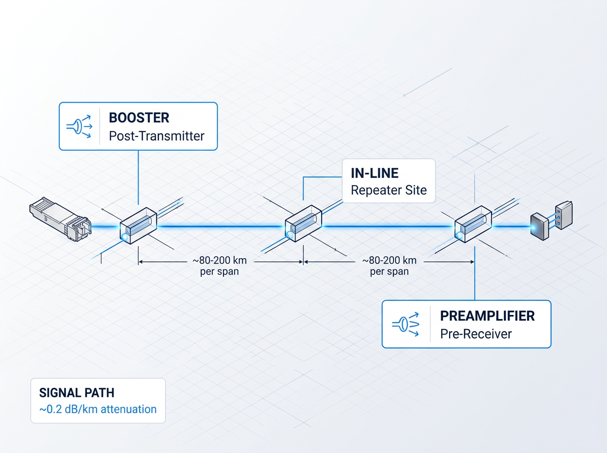
Silica fibre attenuates signals at roughly 0.2 dB/km, capping unamplified reach to around 80–200 km at gigabit-per-second rates. The pre-EDFA answer was OEO regeneration: convert to electrical, apply 3R processing, re-transmit. In a WDM system, each regenerator was bit-rate- and channel-specific — N channels required N regenerators per site, making large-scale WDM economically unworkable.
Optical amplifiers amplify directly in the optical domain, transparent to data rate, modulation format, and channel count. EDFAs displaced OEO regenerators from the early 1990s, enabling transoceanic links at terabits per second. They serve three roles: booster (post-transmitter), in-line (repeater sites), and preamplifier (pre-receiver), each with distinct performance priorities.
Agnostic to Rate and Format
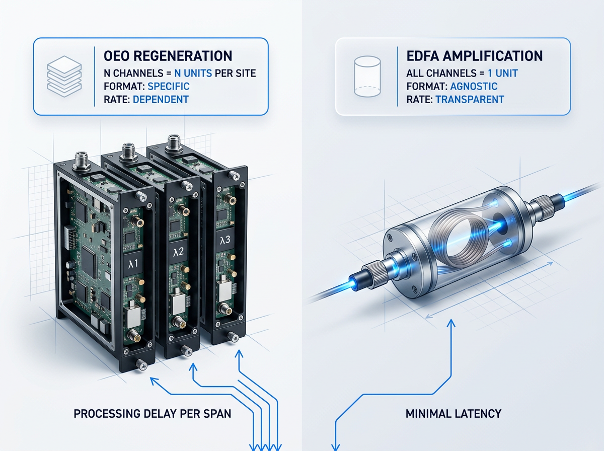
An EDFA amplifies photons, not bits. It carries no knowledge of the data rate or modulation format of the signals passing through it — making it transparent to frame format, modulation scheme, and bit rate simultaneously.
OEO regenerators are inherently format-specific: a 10G NRZ regenerator cannot handle 100G DP-QPSK. Upgrading capacity therefore requires replacing regenerators at every repeater site. With EDFAs, only terminal transponders change. The amplifier infrastructure in the field remains untouched across successive capacity generations — a compounding architectural advantage over any deployed network's lifetime.
One Amplifier, All Channels
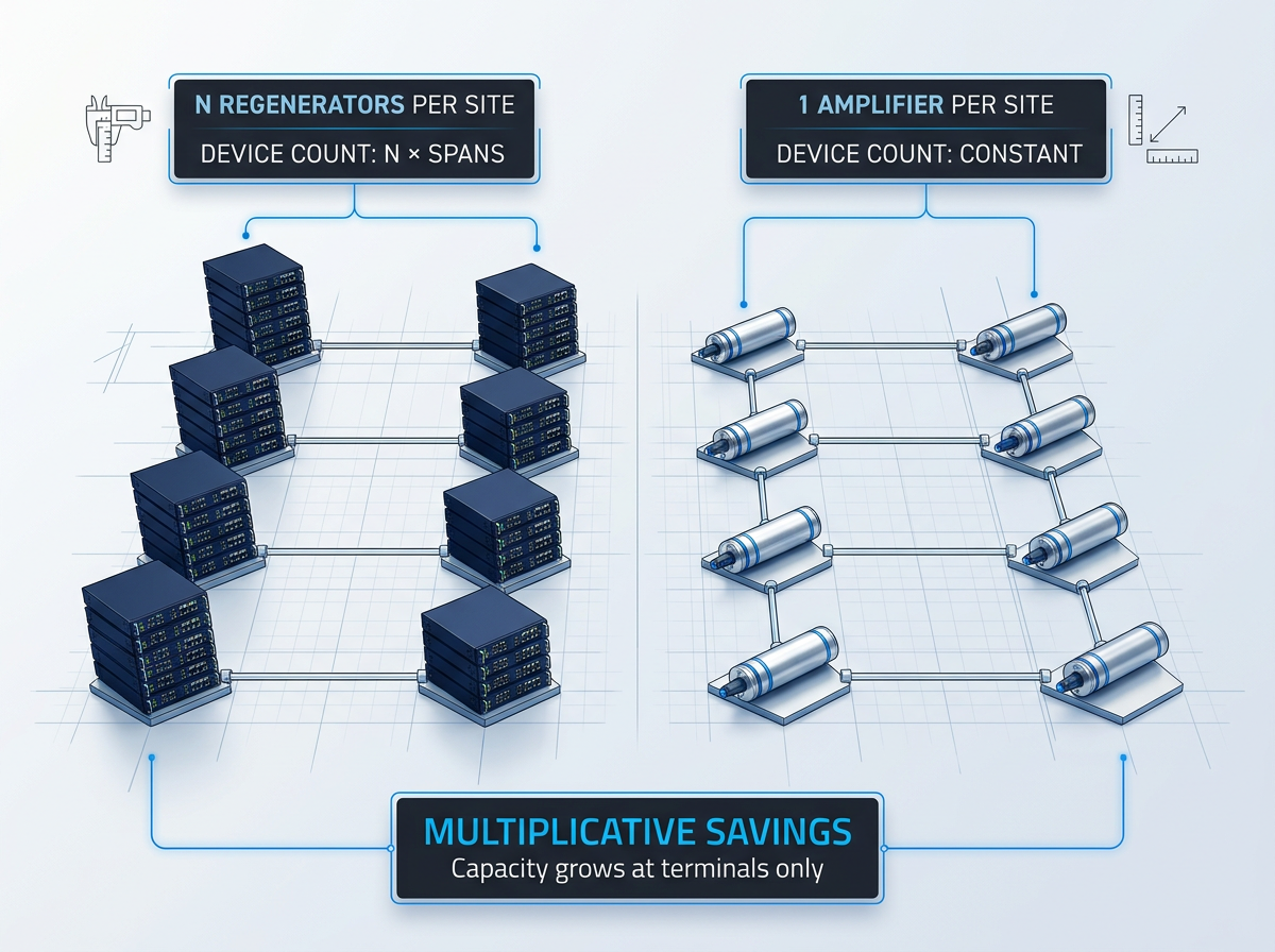
OEO regeneration is channel-specific: a DWDM link carrying N wavelengths requires N regenerators at every repeater site. Device count scales with both channel count and span count — the cost grows multiplicatively across the network.
A single EDFA simultaneously amplifies all co-propagating wavelength channels within its gain band, replacing that entire per-channel stack with one device per site. As IEEE TechNav confirms, this was the key enabler of practical long-haul WDM: the amplifier count does not scale with channel count, fundamentally changing the economics of multi-channel transmission at distance.
Grow Capacity at the Terminals
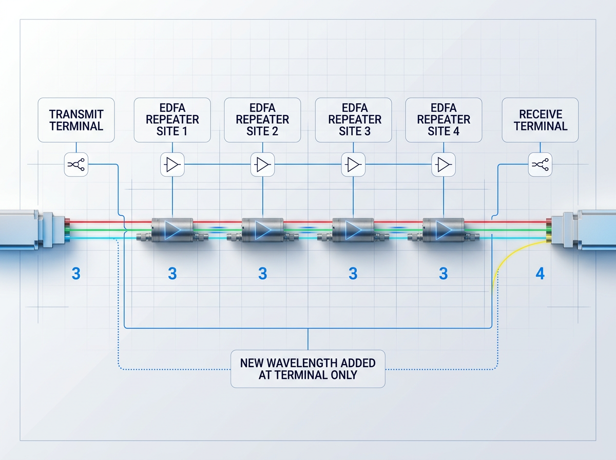
Once EDFA infrastructure is installed at repeater sites, adding wavelength channels requires only upgrading transmit and receive terminals at the network endpoints. The amplifier plant is already in place and will amplify any new channel appearing within its gain band — no field intervention required.
With OEO regeneration, every new channel demands a new regenerator at every repeater site. EDFAs decouple capacity growth from field infrastructure investment, letting operators expand incrementally without re-engineering the repeater network — a structural operational advantage that compounds with each successive capacity upgrade.
Minimal Latency Per Amplifier
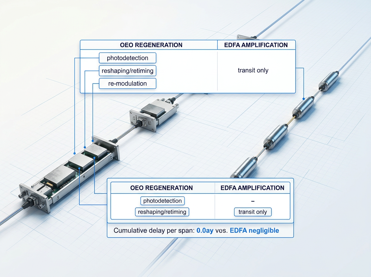
OEO regeneration introduces processing delay at every site: photodetection, electronic reshaping and retiming, then electro-optic re-modulation. Each step consumes time, and those delays accumulate across every regeneration node on a long-haul link.
All-optical amplification contributes only the transit time through the erbium-doped fibre itself — a negligible addition to propagation delay. For latency-sensitive applications such as financial trading infrastructure and real-time control systems, the difference between an OEO architecture and a fully optical one is architecturally significant and grows with every additional span in the link.
Stable, Crosstalk-Free Gain
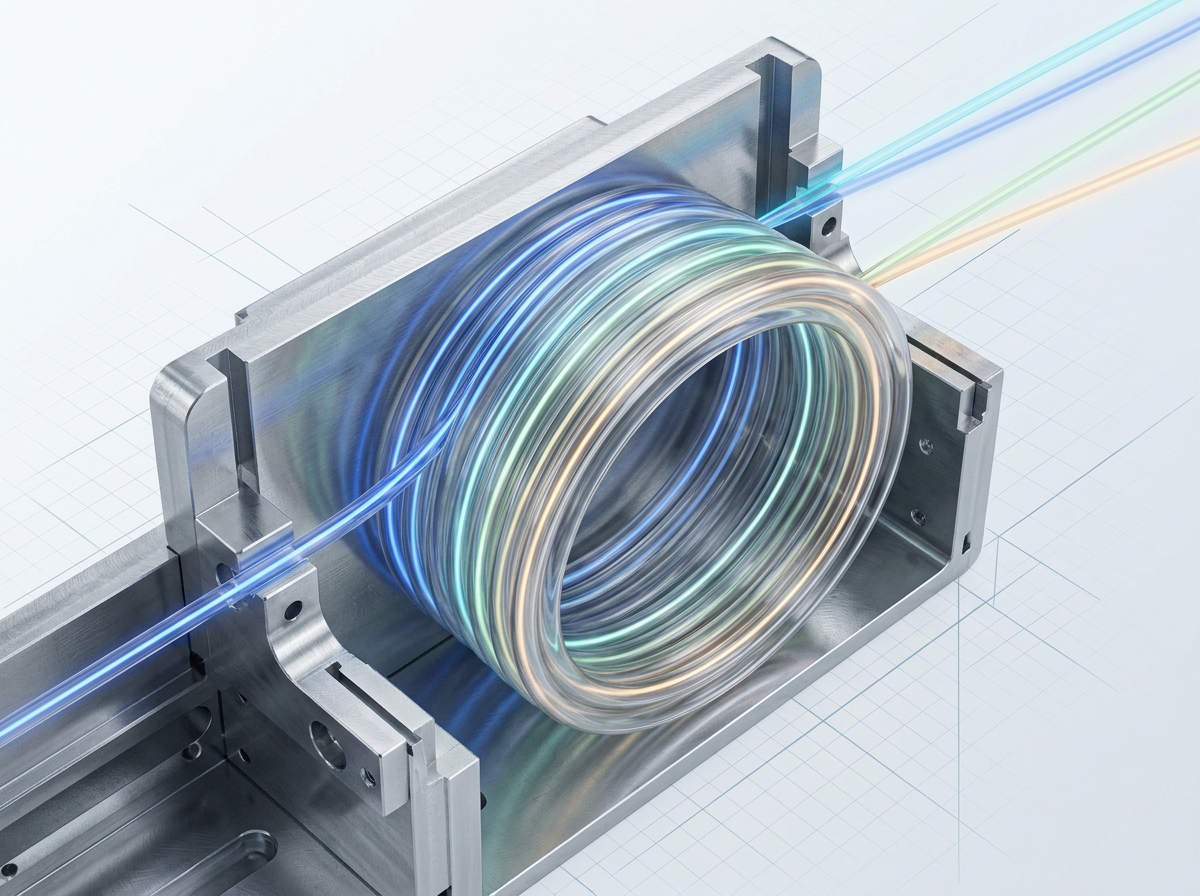
Two signal-quality properties arise directly from erbium-doped fibre physics. First, polarisation-dependent gain (PDG) is typically below 0.5 dB in a single EDFA, making the device essentially polarisation-insensitive and directly compatible with coherent transmission without per-site polarisation management overhead.
Second, the erbium upper-state lifetime of roughly 10 ms means gain cannot respond to individual data bits. The amplifier integrates over millions of bit periods, so a power fluctuation in one DWDM channel cannot modulate the gain seen by another on a bit-by-bit basis — suppressing inter-channel crosstalk inherently.
EDFA Performance Parameters: What Actually Matters
These parameters are interdependent design constraints, not isolated datasheet figures. Their interactions at the real operating point define whether a system performs or fails.
Gain at the Real Operating Point
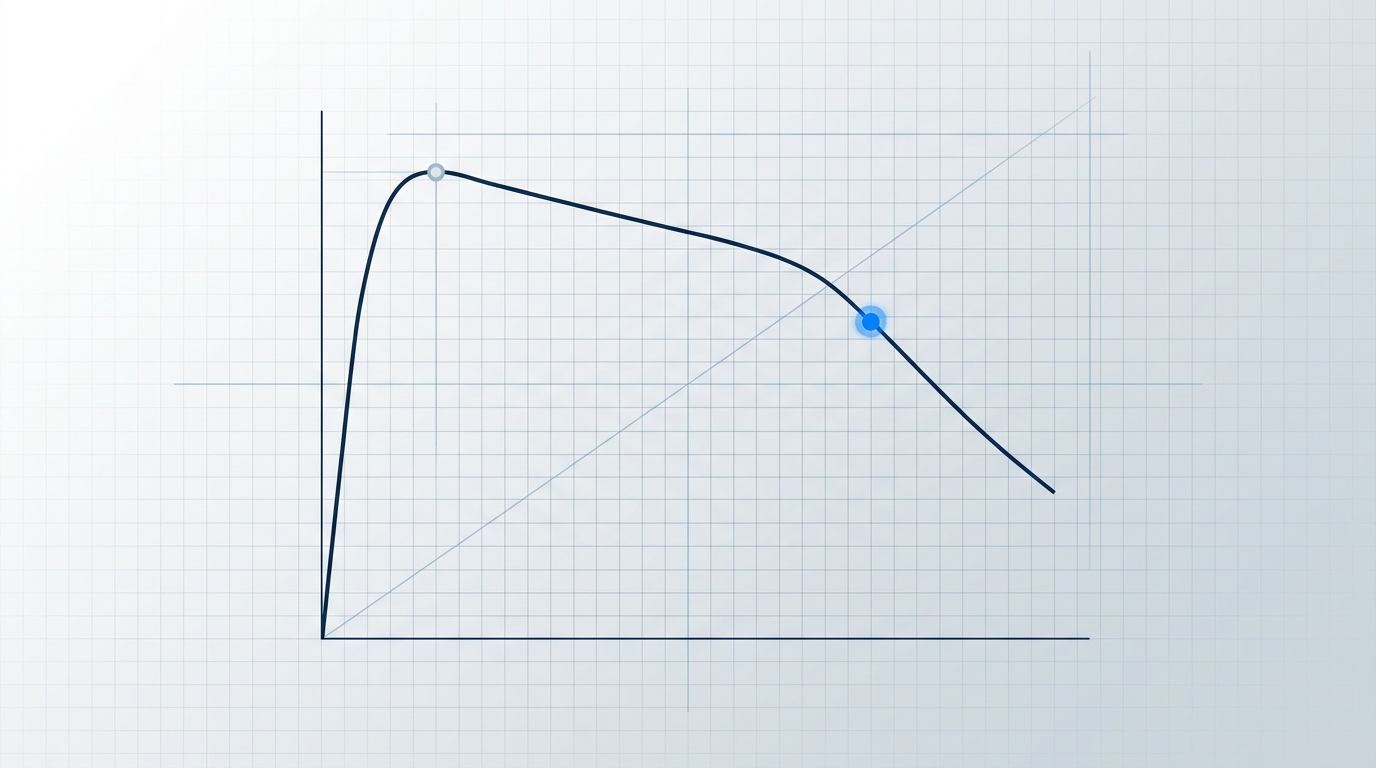
Datasheet small-signal gain is not the figure the system sees. Gain under actual channel loading and input power is what determines link performance.

Noise Figure: The OSNR Constraint in Cascaded Chains
Via the Friis formula, NF compounds across every amplifier stage. A 1-2 dB per-amplifier advantage translates to hundreds of kilometres of additional reach.
980 nm Pumping and the Noise Figure Floor
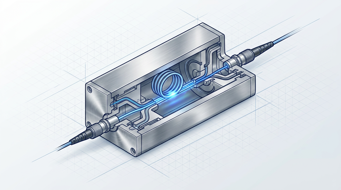
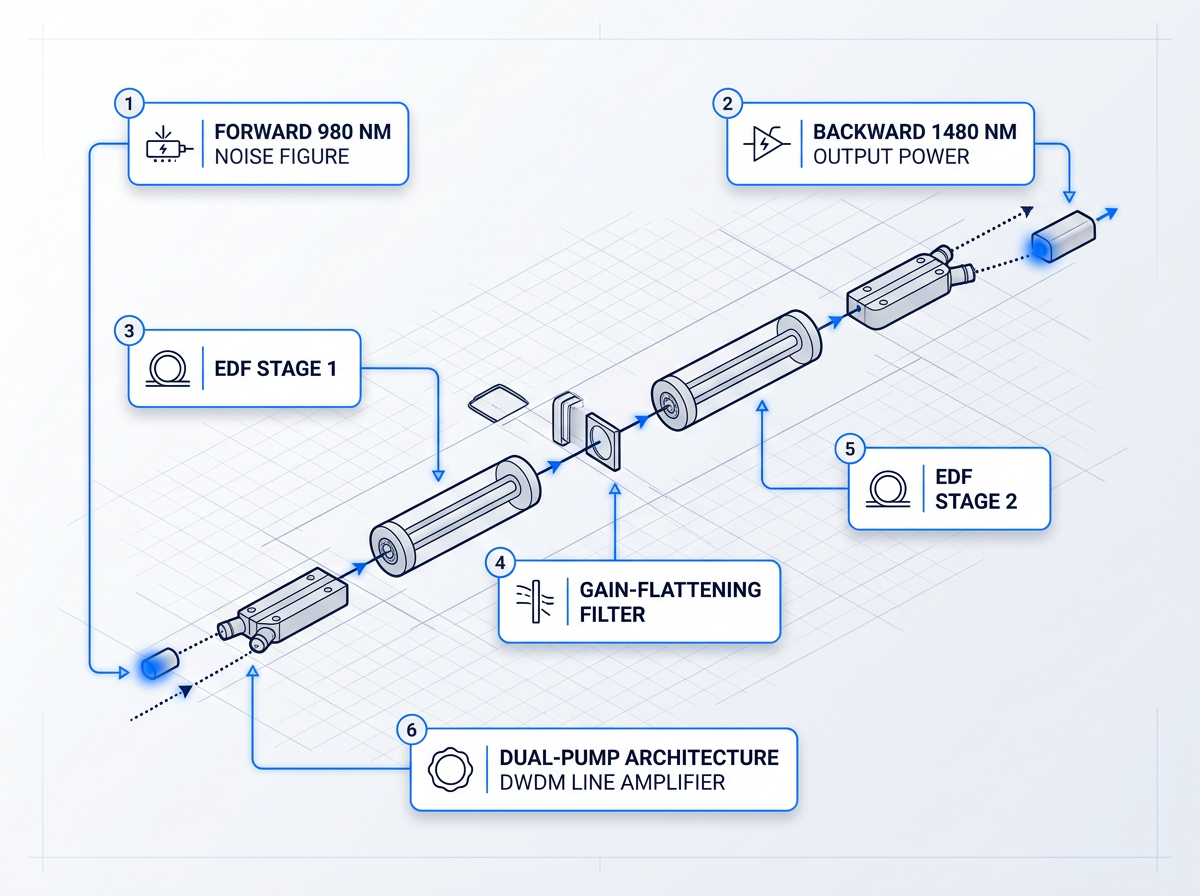
The quantum limit sets a 3 dB NF floor; practical EDFAs reach 4-6 dB. Forward 980 nm pumping achieves lower NF via fuller population inversion.
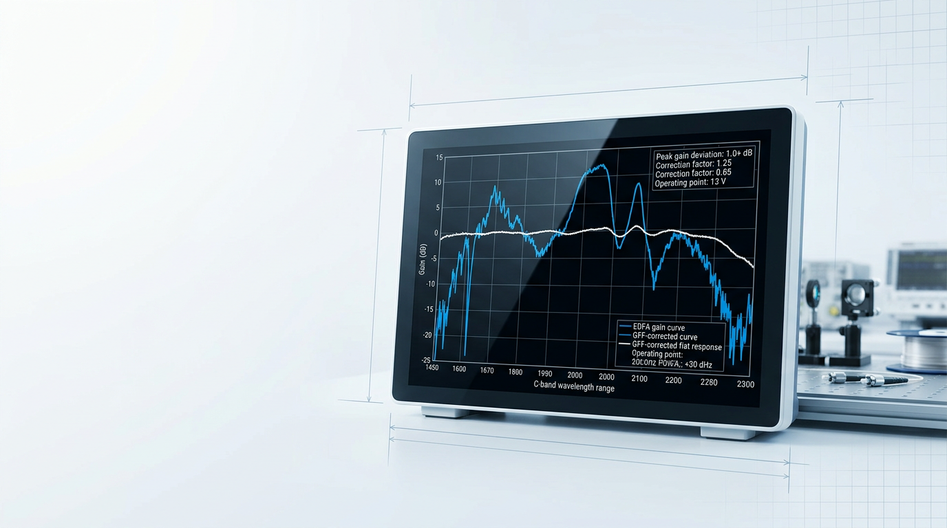
Gain Flatness: Why Raw EDFA Gain Is Unusable
Raw C-band gain varies by 10+ dB across the spectrum. GFFs correct this, but are optimised for one operating point; tilt returns when conditions shift.
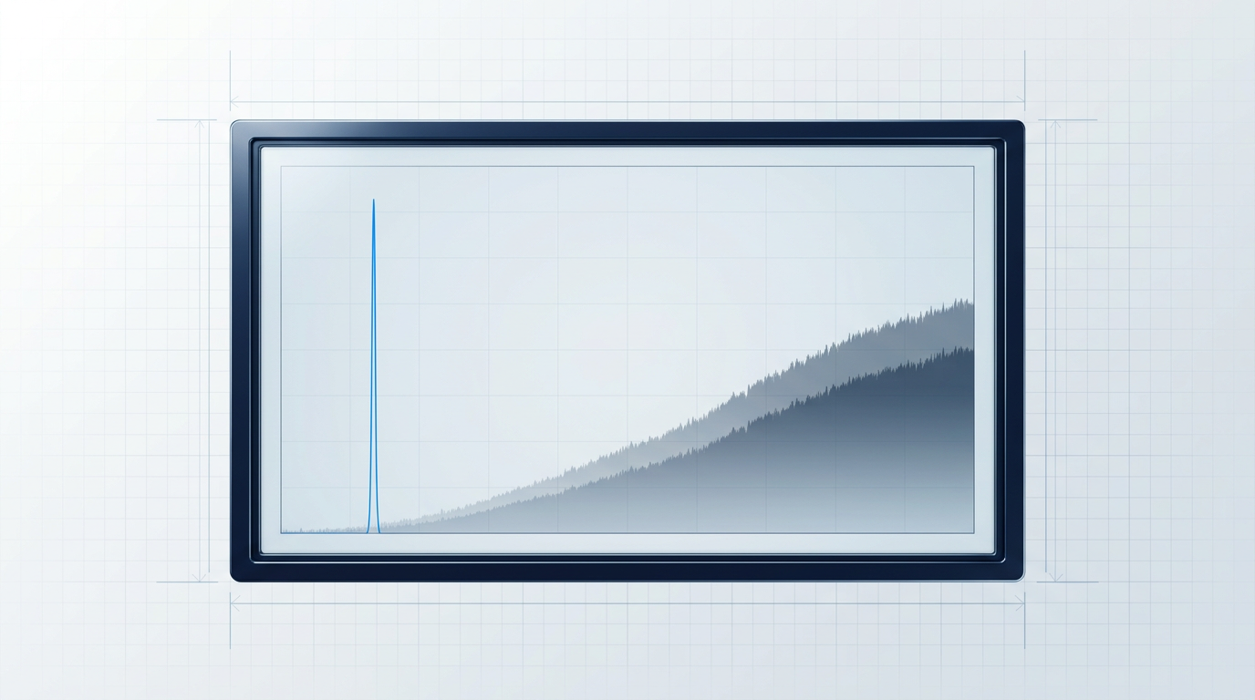
ASE Accumulation Cannot Be Reversed Downstream
Every amplifier in a cascade adds ASE that no downstream stage can remove. Higher output power restores signal level but cannot recover degraded OSNR.
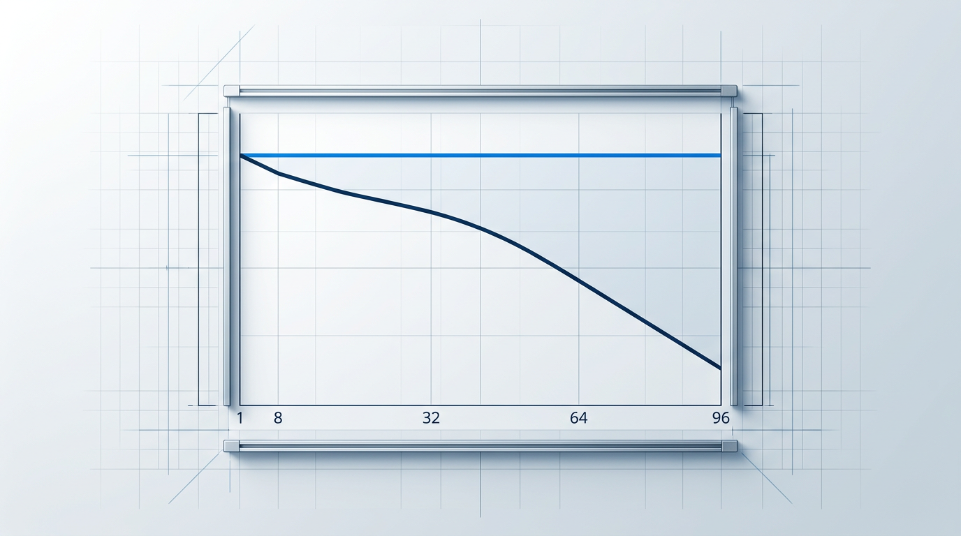
Output Power Must Be Evaluated Under Full Load
Rated saturated output is a total figure. As channel count rises, per-channel power falls. Gain compression at full load is the binding design constraint.
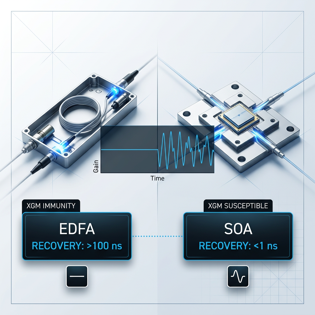
Why XGM Disqualifies SOA
EDFA gain recovery is orders of magnitude slower than a single data bit period. Gain integrates across the full channel population simultaneously, making EDFA inherently immune to cross-gain modulation (XGM) and pattern-dependent crosstalk between co-propagating DWDM channels.
SOA carrier lifetime is short enough for gain to track data modulation directly. In multi-channel environments this causes XGM that degrades signal integrity across all co-propagating channels — a disqualifying limitation for line amplification roles, not a manageable trade-off.
OSNR and Capacity Axis
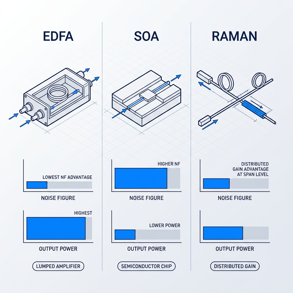
Among lumped amplifier types, EDFA delivers the lowest noise figure and the highest saturated output power — the two parameters that govern OSNR budget and channel capacity in cascaded DWDM systems. SOA noise figure is materially higher and output power is substantially lower, making it insufficient for multi-channel line amplification.
Distributed Raman can achieve an effective noise figure advantage over lumped amplifiers because gain accumulates along the span rather than at a single endpoint. That advantage is real, but pump-limited and distributed by nature — it supplements EDFA on demanding links rather than replacing it.
Band Constraints vs Flexibility
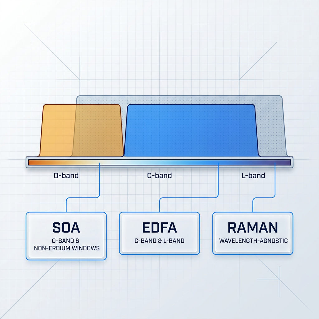
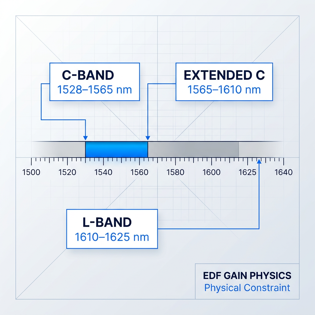
Erbium provides gain only within the C-band and L-band. Outside these windows, no amount of pump power produces gain — a hard physical boundary set by the erbium ion's energy structure, not a product limitation.
Raman amplification is wavelength-agnostic: pump wavelength selection places gain at any target band, making it uniquely capable in spectral regions where no rare-earth dopant operates. SOA coverage is determined by semiconductor material composition, giving access to the O-band and other non-erbium windows. For C/L-band DWDM, EDFA is the correct choice; for other bands, Raman or SOA fills the gap.
Scale and Integration Burden
SOA is a millimetre-scale semiconductor chip fabricated via standard PIC processes — the only amplifier type that integrates natively with silicon photonics and III-V platforms, making it irreplaceable for on-chip amplification in integrated photonic systems.
EDFA occupies a discrete fibre-based module, typically rack-mounted or benchtop, well-suited to line system deployments but incompatible with on-chip integration. Raman carries the highest infrastructure burden: watt-class pump lasers, dedicated optical safety engineering, and significant terminal equipment. It is rarely deployed standalone.

Choosing the Right Technology
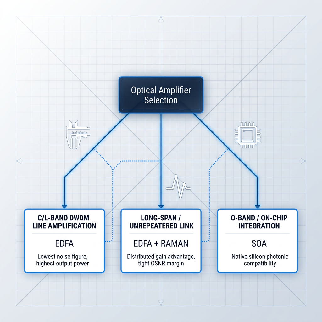
For C/L-band DWDM line amplification — the dominant use case in long-haul terrestrial and submarine networks — EDFA is the default first choice, selected for its noise figure, output power, gain dynamics, and mature deployment ecosystem.
Distributed Raman adds value as an EDFA supplement when OSNR margins are tight, particularly on long or unrepeatered spans. SOA is the correct selection for O-band amplification, on-chip photonic integration, fast optical switching, and wavelength conversion. It is not a drop-in substitute for EDFA in multi-channel line amplification and should not be evaluated as one.
Gain Flatness and Spectral Management in DWDM Systems
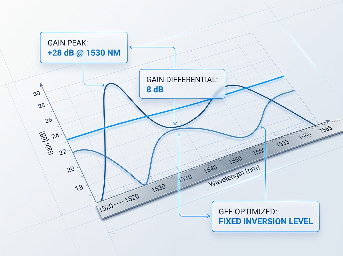
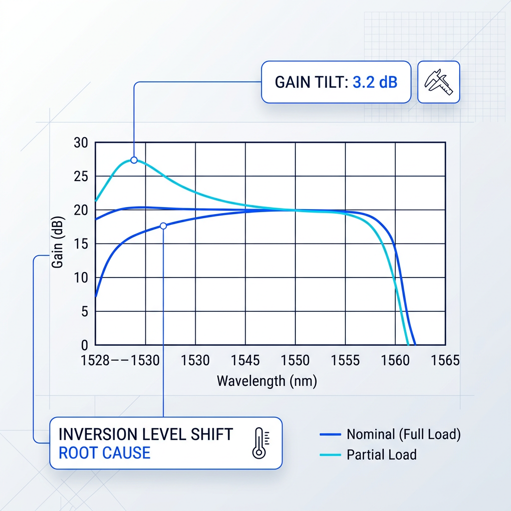
Raw C-band gain non-uniformity is a given — the challenge is what happens to GFF correction when operating conditions shift. A GFF is optimised for one inversion level; deviate through span loss variation or partial channel loading, and gain tilt re-emerges, with peak channels accumulating excess ASE while trough channels lose OSNR margin.
In live ROADM networks, channel add/drop events drive inversion-level transients that reshape the gain spectrum within microseconds. Surviving channels see power excursions that can saturate or starve receivers, making sub-millisecond AGC loop bandwidth a hard requirement. Transient suppression at this speed demands purpose-built control electronics.
Pump Architecture: The Design Variable Behind NF and Power
Forward 980 nm pumping maximises inversion at the signal input end, yielding the lowest noise figure — suited to preamplifiers and noise-sensitive in-line stages. Backward 1480 nm pumping sustains inversion at the output end for higher saturated output power, preferred in booster roles. Dual pumping combines both constraints simultaneously and is the baseline architecture for high-performance DWDM line amplifiers.
In two-stage designs, the GFF sits in the mid-stage: NF is set by the first stage; the second recovers insertion loss. EDF length must be co-optimised with pump power per application — beyond the optimal length, the unpumped tail re-absorbs gain.
Gain Profiles Fixed at Design Point
Catalogue EDFAs are optimised around a single operating point: a defined input power, channel count, and span loss. Operate outside those conditions — partial channel loading, non-nominal input power — and the erbium inversion level shifts, altering the gain spectrum in ways the datasheet does not reflect.
Gain flatness degrades and noise figure worsens. The GFF correction built into the product was characterised at one inversion level; deviate from it, and gain tilt accumulates across every subsequent span.
Standard C-Band Coverage Is Fixed
Catalogue C-band products cover approximately 1528–1565 nm. That boundary is not a configuration limit — it is set by the erbium gain physics of the specific EDF length, dopant concentration, and pump design the product ships with.
Applications requiring extended C-band, L-band (1565–1625 nm), or non-standard spectral allocations cannot be accommodated. The system design ends up conforming to the amplifier's spectral constraints rather than the amplifier being engineered to the system's requirements.
Fixed Pump Architecture Limits Performance
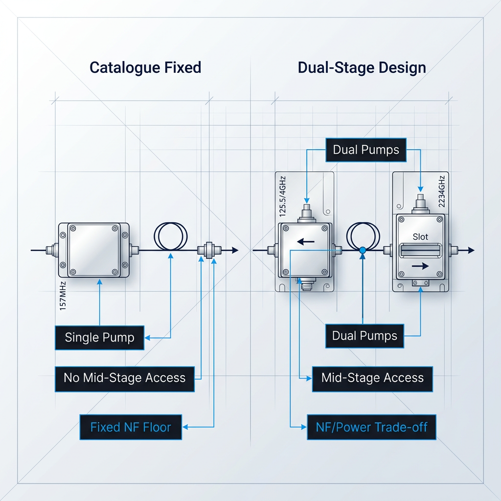
Off-the-shelf EDFAs typically ship with a single-stage, single pump-wavelength architecture. This forecloses dual-stage configurations, mid-stage access for dispersion compensation, and the NF/output-power trade-offs that application-specific designs require.
Compounding this, real DWDM systems vary in input power, channel count, and span loss across their operating lifetime. A catalogue product specified at one rated condition may fail to hold gain flatness or NF across the full dynamic range the live network actually presents.
Datasheets Cannot Predict System Behaviour
A catalogue amplifier is characterised as a standalone device in a controlled test environment. Inserted into a real system, its performance interacts with upstream and downstream components in ways the datasheet cannot capture.
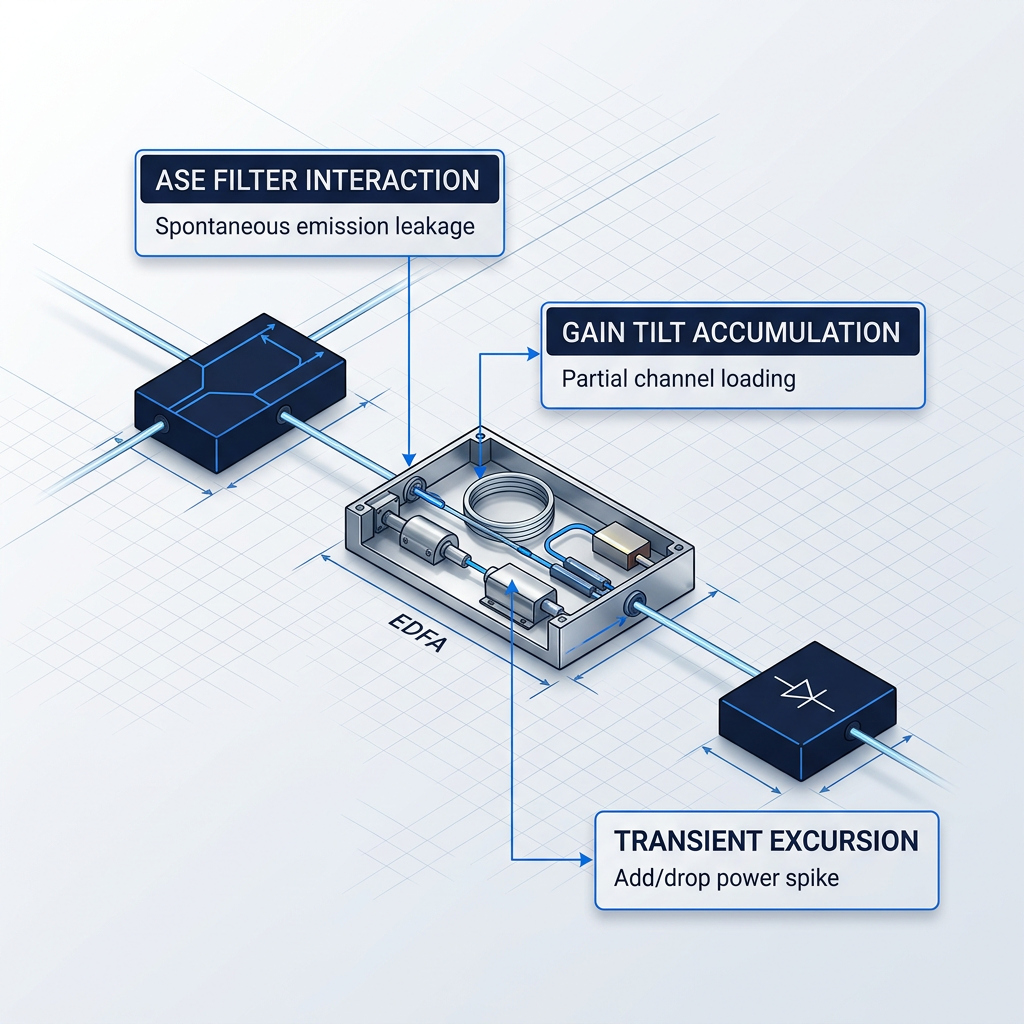
ASE interactions with adjacent filters, gain tilt from partial channel loading, and transient behaviour during add/drop events are all system-level phenomena. These are the surprises that surface during integration and commissioning — not during datasheet review.
A Datasheet Is Not Documentation
Catalogue products are supplied with a datasheet and, at best, a production test report. There is no component-level design documentation, no environmental qualification data, and no traceable record of design decisions.
For deployments where field serviceability is constrained or non-existent, this absence is an engineering risk, not an administrative inconvenience. Traceability and qualification test coverage are requirements — and a catalogue product, by definition, cannot provide design ownership for your specific application.

Applications Where Custom EDFA Design Is Essential
These are not niche edge cases. They represent the mainstream of serious optical network deployment — contexts where performance requirements exceed what catalogue products are designed to meet, and where custom EDFA engineering is the baseline professional expectation, not an optional upgrade.

Long-Haul Terrestrial DWDM
OSNR accumulation across 20-30 cascaded stages demands tight NF control catalogue products cannot guarantee.

Repeatered Submarine Cable Systems
A 25-year design life with no field serviceability makes catalogue selection categorically unsuitable.
DWDM Metro and ROADM Networks
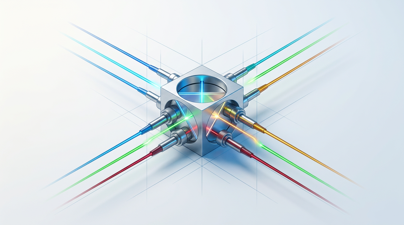
Fast transient control and stable gain flatness under partial channel loading are non-negotiable requirements.
Defence and Aerospace Deployments
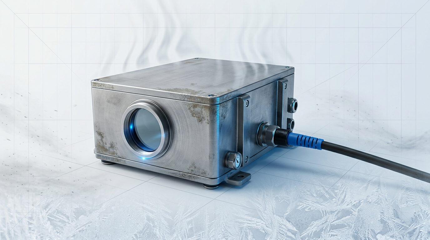
Operating temperature ranges beyond -5 to +65°C Telcordia limits disqualify standard commercial EDFAs.

Scientific Instrumentation and Sensing
Narrow-linewidth amplification and polarisation-maintaining output are requirements no catalogue product addresses.
Unrepeatered Submarine Links
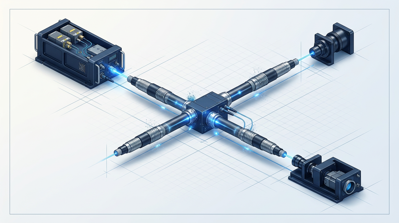
Hybrid booster EDFA, Raman, and ROPA architectures require system-level co-engineering, not catalogue selection.
Engineering to Specification: How Custom EDFA Design Works
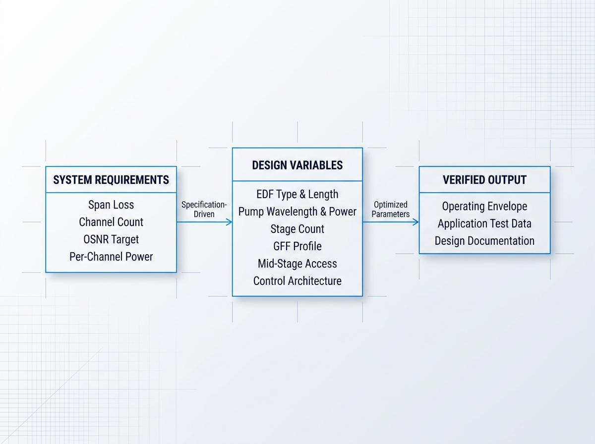
Custom EDFA design starts from the system's link budget and channel plan — span loss, channel count, per-channel power, required OSNR — and works backward to the amplifier parameters that must be met. Catalogue selection does the opposite: it starts from a datasheet and hopes the system fits.
From that specification, the engineer controls EDF type and length, pump wavelength and power, stage count, GFF profile, mid-stage access components, and control architecture. Each variable is optimised to the application. The output is a verified operating envelope with application-specific test data and full design documentation — baseline expectations, not extras.
Custom EDFAs Engineered to Your System Specification
When catalogue products cannot meet your noise figure, wavelength, or gain requirements, a tailored EDFA is the answer. Explore how our custom EDFA solutions are designed around your application.

Frequently Asked Questions
Practical engineering questions and common queries about optical amplifiers and EDFAs, answered directly.
When performance requirements are well-defined and margins are tight. The clearest triggers: non-standard wavelength coverage (extended C-band, L-band, or non-standard spectral windows), demanding noise figure targets that catalogue products cannot reliably meet across the full dynamic range, wide gain dynamic range under variable channel loading, and mission-critical reliability requirements with full design documentation and traceability — submarine, defence, and scientific instrumentation being the canonical cases. System-specific integration is another driver: when standalone datasheet performance is insufficient to predict behaviour in the actual link, a design engineered to the system's own link budget is the only defensible approach. For applications where specifications are loose and margins are wide, a catalogue product may be entirely adequate. The case for custom engineering rests on the specificity of the requirement, not the prestige of the application.
Practical EDFAs achieve 4–6 dB noise figure; the theoretical floor set by quantum mechanics is 3 dB. That 1–3 dB gap above the quantum limit is where amplifier design either wins or loses OSNR budget. In a cascaded amplifier chain, noise figure compounds via the Friis formula — each stage adds ASE that no downstream amplifier can remove. A 1–2 dB per-amplifier NF improvement translates directly into meaningful OSNR margin at the receiver, often the difference between a link budget that closes and one that does not. Pump wavelength is a key design variable here. Forward 980 nm pumping achieves lower NF than 1480 nm pumping because it produces more complete population inversion at the signal input end of the erbium-doped fibre. This makes 980 nm forward pumping the preferred configuration for preamplifiers and noise-sensitive in-line stages, where NF is the binding constraint rather than output power.
Not completely. An optical amplifier restores signal power in the optical domain but does not perform 3R regeneration — it does not retime, reshape, or retransmit the signal. Accumulated ASE noise, chromatic dispersion, and nonlinear impairments are not corrected; they are carried forward. What optical amplification does provide — simultaneous amplification of all WDM channels without OEO conversion, full protocol and format transparency, and near-zero latency — makes it the preferred repeater technology for the vast majority of modern fibre-optic links. OEO regeneration at defined intervals remains necessary when accumulated impairments degrade the signal beyond what the receiver can tolerate. In practice, modern coherent DSP at the terminals has substantially extended the reach of optically amplified links, reducing the frequency at which OEO regeneration is required in long-haul systems. The two technologies are complementary, not mutually exclusive — the engineering question is where along the link OEO regeneration, if any, is needed.
An optical amplifier increases the power of an optical signal directly in the optical domain, without converting it to an electrical signal. This transparency preserves the signal's data rate, modulation format, and wavelength simultaneously — the amplifier has no knowledge of what it is amplifying. In practice, optical amplifiers are deployed in three distinct roles. A booster amplifier is placed immediately after the transmitter to maximise launch power into the first fibre span; output power is the priority here. An in-line amplifier sits at repeater sites along the route to compensate for accumulated span loss; it balances output power and noise figure. A preamplifier is placed just before the receiver to improve detection sensitivity; noise figure is the critical parameter, as any noise added at this stage directly degrades the receiver's OSNR. Each role carries different design priorities, which is why a single catalogue specification rarely optimises for all three simultaneously.
The primary advantages are protocol transparency, simultaneous multi-channel amplification, format agnosticism, low latency, and pay-as-you-grow capacity scalability. Protocol transparency means a single EDFA amplifies any signal within its gain band regardless of bit rate or modulation format — upgrading from 10G to 100G to 400G requires only terminal equipment changes, not new amplifiers in the field. WDM cost leverage is substantial: one amplifier simultaneously replaces N OEO regenerators, one per channel, at every repeater site. The cost advantage scales multiplicatively with channel count and span count. Latency is another axis: all-optical amplification adds sub-nanosecond delay per site versus microseconds of processing delay through each OEO regeneration node — a material difference for latency-sensitive traffic. Finally, once fibre and amplifiers are installed, additional WDM channels are activated by upgrading only transmit and receive terminals. The amplifier plant requires no modification, making capacity growth a terminal-side decision rather than a network-wide infrastructure change.
EDFA dominance originates from a physical coincidence: the erbium gain band aligns with the lowest-loss transmission window of standard silica fibre, the C-band (1530–1565 nm). This is not a design preference — it is a material property that makes EDFA the natural amplifier for the wavelengths fibre already propagates most efficiently. Three factors reinforce that foundational advantage. First, noise figure: practical EDFAs achieve 4–6 dB NF, approaching the 3 dB quantum limit, giving them the best OSNR performance of any lumped amplifier type. Second, gain dynamics: the millisecond upper-state lifetime of erbium ions means EDFA gain cannot respond to individual data bit transitions, making the gain effectively constant across all co-propagating WDM channels and eliminating inter-channel crosstalk. Third, ecosystem maturity: three decades of deployment have produced a deep supply base of pump lasers, gain-flattening filters, and control electronics optimised specifically for EDFA operation — a practical engineering advantage that compounds over time.