

Introduction
If you're an engineer, production manager, or operations decision-maker who has started asking serious questions about automated metal finishing, you're probably not at the beginning of that conversation.
You already know finishing matters — and you've likely felt the point where manual methods stop being good enough.
This guide is written for that moment: when the operational case is taking shape and what you need is genuine depth, not a surface-level overview.
It covers the full picture — processes, equipment, system design, integration, and the harder questions around cost justification and compliance — with the specificity that production thinking demands.
TL;DR
Automated metal finishing is a well-established industrial capability with a clear evaluation framework — once you understand the processes, the system architectures, and what drives real-world ROI. The gap between "we should automate this" and a justified, implementable plan is smaller than it looks when you have the right information.
This article covers:

The main automated finishing process families and how to identify which applies.
Why manufacturers move from manual finishing and what drives the case.
The hardware inside a finishing cell and how each component affects output.
Standalone cells vs. integrated lines: architectural decisions and trade-offs.
Integration planning, line design, and building a credible business case.
Process control, quality assurance, and regulatory compliance requirements.
What Is Automated Metal Finishing?
Automated metal finishing covers more ground than the phrase might initially suggest. It is not simply mechanised polishing or a robot holding a grinder — it is a broad category of controlled, repeatable, programmable processes that spans everything from removing a burr on a machined casting to electroplating a medical implant, and the systems that perform them range from single-purpose belt machines to fully integrated production lines.
At its core, automated metal finishing is the use of robotic and mechanised systems to perform surface finishing operations on metal parts that would otherwise be done by hand. The hardware involved includes force-controlled robots, CNC-driven finishing equipment, dedicated single-purpose finishing machines, and conveyor-integrated lines — each suited to different part geometries, volumes, and finish requirements.
The scope of "finishing" in industrial practice is broader than surface appearance alone. It encompasses mechanical operations such as deburring, edge rounding, grinding, polishing, and surface smoothing; surface preparation work including the removal of oxides, mill scale, weld discolouration, and contamination to ready parts for coating or bonding; and wet-process treatments that chemically alter or deposit material on the surface.
The Main Process Families at a Glance
Automated finishing work falls into three major families, with surface preparation acting as a cross-cutting pre-step across all of them. The next section of this guide examines each family in operational depth — what follows is the orientation map.
- Mechanical finishing: Deburring, edge rounding, grinding, polishing, and surface smoothing — removing material or refining surface texture using abrasive or cutting contact.
- Mass and vibratory finishing: Parts are processed in bulk within a moving media bed. Sub-types include circular vibratory, trough vibratory, drag finishing, and centrifugal systems.
- Wet-process finishing: Chemical and electrochemical treatments: electroplating, anodising, electropolishing, passivation, and conversion coatings that alter or deposit surface layers.
- Surface preparation: Removal of oxides, mill scale, rust, and contamination — a cross-cutting pre-step that conditions parts before mechanical or wet-process finishing.
The defining difference between automated and manual finishing is not speed — it is consistency. A force-controlled robot or a programmed finishing machine applies the same contact force along the same path on every cycle, regardless of operator fatigue, skill variation, or shift changes. Manual finishing, by contrast, produces variable output: different operators apply different pressure and technique, and the same operator's output drifts as the shift progresses.
In automated finishing, the process itself holds the standard — output quality is built into the programme, not dependent on who is running the shift.
It is also worth recognising that automation in finishing exists on a spectrum, not as a single configuration. At one end sit semi-automated dedicated machines — belt deburring equipment or vibratory finishing systems that automate the finishing action but still require manual part loading and unloading.
Further along the spectrum are fully robotic cells: articulated robots carrying force-controlled spindles or compliant tooling that handle complex three-dimensional geometries and adapt contact force in real time.
At the most integrated end are automated production lines where finishing is one step in a continuous flow, with automated material transfer between operations and centralised process control across the entire sequence.
Automated metal finishing is established practice across automotive, aerospace, medical devices, heavy equipment, and electronics manufacturing — industries where surface quality directly affects function, durability, coating adhesion, or regulatory acceptance.
With the category defined and the process families mapped, the next section examines each one in detail — what it involves, how automation changes it, and what output specifications it targets.
The Main Process Types in Automated Metal Finishing
The equipment you need, the system architecture that makes sense, and the business case you can build all depend on one thing first: which process your parts actually require.
Automated metal finishing is not a single process — it is a family of fundamentally different approaches, each suited to different part geometries, material conditions, and output specifications. Choosing the right automation path starts with understanding which process family applies.
Mechanical Finishing
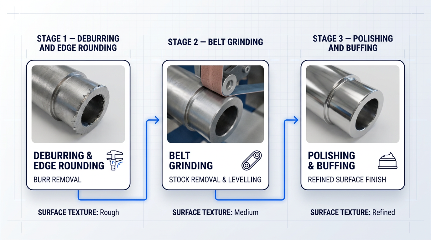
Deburring and edge rounding address one of the most pervasive quality issues in machined, stamped, cut, and welded metal parts: the burr.
A burr is raised or displaced material left at a part edge after a cutting or forming operation. Left in place, burrs compromise assembly fit, act as stress concentration points that reduce fatigue life, interfere with paint and coating adhesion, and present a direct safety hazard during handling.
Automated deburring takes two distinct forms depending on part geometry and production volume. For complex 3D geometries with variable edge conditions, force-controlled robotic spindles follow a programmed path while adapting in real time to surface variation, maintaining consistent contact and producing a controlled edge radius regardless of part-to-part dimensional variance.
For high-volume parts with consistent, repeatable geometry, dedicated brush or belt deburring machines are the more productive choice — fixed tooling, fast cycle times, and no need for the flexibility that a robotic cell provides.
Belt grinding is the workhorse of automated stock removal. It handles weld bead blending, surface levelling, and dimensional correction across a wide range of part types, using ceramic or aluminium oxide abrasive belts in multi-stage sequences that progress from aggressive stock removal through to a controlled final surface condition.
What automation contributes to grinding is path and pressure consistency. A human operator varies their applied force and dwell time across a shift; an automated system holds the same belt pressure and traversal speed on every part — and it is that repeatability which makes a defined surface roughness target achievable run after run.
Polishing and buffing serve two distinct purposes: functional surface preparation (typically pre-plating or pre-coating, where surface condition directly affects adhesion and deposit quality) and cosmetic finishing (appearance-grade surfaces for consumer products, architectural components, and premium hardware).
Achieving a mirror or near-mirror finish requires multi-stage progressive refinement — starting with coarser cutting compounds to remove the substrate's existing surface texture, then working through progressively finer compounds until the required reflectivity is reached. Robotic polishing is now viable even for complex, contoured geometries because force control maintains consistent compound pressure against the surface regardless of changes in contour, something a fixed-spindle machine cannot do.
Mass and Vibratory Finishing
Mass finishing — also called trowalising — operates on a fundamentally different principle from robotic or machine-based mechanical finishing. Parts and abrasive or polishing media are loaded together into a bowl, trough, or drum, and controlled motion causes the media to act across every exposed surface of every part simultaneously.
The practical significance of this is that media reaches internal bores, undercuts, recesses, and complex geometries that a robotic arm or belt machine cannot practically access. A single vibratory bowl cycle can deliver surface smoothing, deburring, edge rounding, cleaning, and degreasing in one operation — making it particularly efficient for high-volume batches of small or medium-complexity parts.
Specific configurations include vibratory bowl finishers, which use oscillating motion to drive media against parts, and drag finishing machines, where individual parts are mounted on fixtures and dragged through a rotating media mass — giving tighter control over edge geometry and surface finish on higher-value components.
Automation in mass finishing is not about robotic motion. It is about controlled process parameters: amplitude and frequency of vibration, cycle time, media type and size, compound concentration, and dosing intervals. Automated systems manage these variables precisely and repeatably, producing consistent output across large batch quantities where manual loading and parameter adjustment would introduce run-to-run variation.
Wet-Process Finishing
Wet-process finishing covers any treatment that applies or modifies a surface layer through chemical or electrochemical action. The main processes in this family include electroplating (depositing a metallic layer for corrosion protection, conductivity, or appearance), anodising (building an oxide layer on aluminium for hardness and corrosion resistance), electropolishing (electrochemically dissolving surface peaks to produce a smooth, passive finish), passivation (treating stainless steel to restore its chromium oxide layer), and chemical conversion coatings such as chromate or phosphate treatments.
The automation architecture for wet-process lines centres on automated hoists and conveyor systems that move part carriers through a sequence of process tanks — pre-treatment, rinse, active chemistry, rinse, and post-treatment — under recipe-driven process control.
What automation delivers here is immersion time accuracy and bath chemistry stability. In a manual line, an operator's timing variation of even a few seconds per tank can produce measurable differences in deposit thickness or oxide layer depth; automated systems control immersion to the second, and auto-dosing of chemistry maintains bath concentration within a defined specification window throughout the shift.
Every part's process record — tank sequence, immersion times, bath chemistry readings, hoist movements — can be logged automatically, creating a traceable quality record that manual operations cannot practically generate at the same level of detail.
Before any of the three process families can be applied, parts typically require surface preparation and cleaning as an upstream step. Oxides, mill scale, machining oils, drawing compounds, and handling contamination must be removed before coating, bonding, or further finishing — because residual contamination compromises adhesion and process reliability downstream. This pre-step, whether performed by chemical cleaning, abrasive blasting, or other methods, is integrated into the automated finishing workflow rather than treated as a separate activity.
Because automated wet-process lines log every parameter for every part — immersion time, bath concentration, hoist position, cycle timestamp — they generate a quality record that is structurally impossible to replicate with manual operation. For industries where process traceability is a customer or regulatory requirement, this is not a secondary benefit: it is a core capability that manual lines cannot offer.
With the process landscape mapped, the natural next question is why manufacturers invest in automating these processes at all — and what the specific pain points of doing them manually look like in practice.
Why Manufacturers Move from Manual to Automated Finishing
Finishing is a paradox in the production chain. It is typically the last operation before a part moves to coating or assembly, which means it sits at the point of maximum accumulated value — and yet it is also the step where quality control is most dependent on individual human judgement, physical endurance, and the consistency of effort sustained across an eight-hour shift. That structural tension is why manual finishing departments are so frequently the source of scrap, bottlenecks, and safety incidents, regardless of how well-trained the workforce is.
Variability Is Structural, Not a Training Problem
When the human body is the control mechanism, process variability is not a failure of training — it is an inevitable property of the system.
Different operators apply different pressure and follow different tool paths across a surface, producing different finishes from the same drawing. The same operator's output shifts across a shift: as fatigue accumulates, the force applied to a grinder changes, edge breaks become inconsistent, and the likelihood of over-grinding through a surface increases. As Daniel Webster, engineering manager at OMS, noted after the company automated its deburring operation: "With manual grinding, results differed from employee to employee — one worker would always round the edges a bit more than the next."
That part-to-part variation compounds downstream. Dimensional inconsistencies in edge profiles cause fit problems at assembly; finish inconsistencies cause adhesion failures in coating; missed burrs in recesses pass through inspection and generate field returns.
Automated finishing cells hold the same force, path, and speed on every cycle, regardless of which shift is running or how many hours into the shift the machine is operating. The OMS case illustrates the outcome directly: after automating, the fabricator reported repeatable part quality and the elimination of the scrap that had accumulated at the end of each manual shift.
Labour Scarcity Creates a Production Bottleneck
Manual grinding and deburring is physically demanding, repetitive, and often classified as an entry-level role — a combination that produces chronically high turnover in finishing departments.
The operational consequence is not simply a headcount problem. When finishing cannot be staffed reliably, it becomes the throughput bottleneck for the entire production line: cut parts pile up waiting for deburring; welded assemblies queue for grinding; coating and assembly operations sit idle downstream. OMS, a fabricator operating in a low-unemployment manufacturing state, found itself running up to eight people across three shifts just to keep the grinding department moving — and still fell nearly two weeks behind schedule.
Tink Inc., a manufacturer of heavy lifting and excavation equipment, described the same pattern: at peak, five to ten people were manually grinding parts, positions were difficult to fill, and turnover was high because the work is physically gruelling across a full shift. After automating, the company moved from multiple operators to a single machine operator, with the automated system handling approximately 90% of parts produced.
The cascade effect matters here. Labour scarcity in finishing does not just slow finishing — it throttles every upstream operation that feeds it and every downstream operation that depends on it.
Occupational Hazards Are Inherent to Manual Abrasive Work
The injury profile of manual finishing departments is well-documented and specific to the nature of the work, not to operator carelessness.
Hand-arm vibration syndrome (HAVS) — sometimes called white finger syndrome — develops through prolonged use of handheld grinding tools. Continuous vibration exposure causes circulatory damage that presents as discolouration, numbness, and progressive loss of manual dexterity in the fingers. Because frequent breaks are required to limit exposure, HAVS is also a direct productivity constraint, not just a health one.
Beyond vibration, manual finishing workers face lacerations from sharp burrs and cut edges; crush injuries when heavy plasma- or oxyfuel-cut plates must be manually flipped to deburr both faces; and foreign-object injuries from sparks and ejected metal debris. Tink Inc.'s owner noted that most of the company's foreign-object injuries occurred specifically in the grinding department, where new workers engaging in physically demanding work over a full shift were statistically at greatest risk.
Respiratory exposure to metal dust and fume is a further documented hazard, particularly when grinding stainless steel, aluminium, or coated materials. Automated finishing removes operators from the hazardous work envelope entirely — the machine performs the abrasive action, and the operator's role shifts to loading, unloading, and monitoring.
Finishing Errors Destroy Maximum Accumulated Value
The economic argument for quality control at the finishing stage is not symmetrical with quality control earlier in the process chain.
A part that reaches the finishing stage has already absorbed the cost of every upstream operation: laser or plasma cutting, bending, welding, and any intermediate machining. When a manual finishing error — over-grinding through a surface, a missed burr in a recess, an inconsistent edge break — causes that part to be scrapped, all of that upstream value is destroyed at the worst possible moment.
Finishing is typically the last operation before coating or assembly, which means a scrap event at this stage destroys more accumulated upstream value than a defect introduced at any earlier point in the process chain. The further downstream the error, the more expensive it is.
Manual finishing errors are also largely irreversible. Material removed by over-grinding cannot be replaced; a scratch introduced on a polished surface requires rework that may itself risk further damage. Automated systems — holding consistent force and path parameters on every cycle — structurally reduce the frequency of these error modes.
Cycle Time Predictability Underpins Line Balancing
The throughput advantage of automated finishing is often framed as speed, but the more operationally significant benefit is cycle time consistency.
A manual operator's effective output rate is not constant across a shift. Fatigue slows loading, repositioning, and grinding pace; distraction introduces variation in load/unload time; and the combination makes it impossible to predict with precision how long a production run will take. As Modern Machine Shop has observed, knowing the machining cycle time alone is insufficient for production planning — the variability in human-dependent load and process time is itself a scheduling liability.
Automated cells convert those variable times into fixed, repeatable values. That predictability is what enables reliable line balancing: upstream cutting and welding operations can be scheduled against a finishing throughput figure that does not degrade across the day, and downstream coating or assembly can be fed at a consistent rate.
Skilled Finishers Are Increasingly Difficult to Replace
The turnover problem in entry-level finishing roles is compounded by a separate, more acute shortage at the skilled end of the spectrum.
Experienced manual finishers and polishers — those capable of producing consistent results on complex geometries, tight surface specifications, or high-value materials — represent a craft skill that takes years to develop and is increasingly difficult to recruit. Modern Machine Shop has noted that companies often find it extremely difficult to replace personnel trained in manual material removal processes after they leave, precisely because the knowledge is embodied and not easily transferred.
The firearms manufacturing sector illustrates the dynamic clearly: the departure of craftsmen who spent entire shifts manually polishing pistol and rifle barrels has driven manufacturers to seek automated alternatives, because the human skill pool capable of replicating that work is shrinking. In high-specification aerospace contexts, turbine blade refurbishment historically required extensive hand polishing and carried high scrap rates as a direct consequence of manual process variability.
Automation encodes the required process parameters into the system rather than into the operator. The specialist knowledge shifts from the production floor to the programming and setup stage, which means a smaller number of skilled people can sustain consistent output across a much larger volume of parts.
These problems do not operate independently. Labour scarcity worsens the throughput bottleneck; bottleneck pressure creates urgency that increases variability and the risk of over-grinding; higher scrap rates amplify the cost of every labour hour spent in the department. Automation addresses the structural root of the cascade rather than patching individual symptoms.
Understanding why manual finishing produces these outcomes is the foundation for understanding how automated systems are engineered to avoid them — which is where the hardware discussion begins.
Inside a Finishing Cell: Equipment and Hardware
Knowing why to automate finishing is one thing; knowing what the hardware actually looks like is another. A finishing cell is not a single machine — it is a system of interdependent components, and the output quality of the whole depends on how well each element is selected and integrated.
Robotic Arms: The Core Motion Platform
The 6-axis articulated robot is the dominant motion platform in robotic finishing cells, and for good reason: six axes of rotation give the robot the ability to approach any point on a part surface from virtually any angle, which is essential when working around complex castings, weld assemblies, or machined components with recesses and undercuts.
Three parameters govern robot selection for a finishing application: reach (which determines what part sizes and spatial configurations the robot can address), payload (which determines what tooling and force sensors can be carried at the wrist), and repeatability (which determines how consistently the robot returns to a programmed position across thousands of cycles).
The choice between an industrial robot and a collaborative robot (cobot) is a use-case decision, not a quality hierarchy: industrial robots are the right tool where aggressive material removal loads and high throughput are the priority, operating behind safety fencing with high-speed spindles and heavy tooling; cobots are the right tool where operating near personnel, or fitting into a constrained production space, is the operational requirement — accepting lower force limits in exchange for flexibility.
The robotic arm provides the motion platform, but motion alone does not produce a consistent finish — what the arm does when it contacts the part is determined by a separate and equally critical system.
Force and Torque Sensing: The Defining Technology
Without force control, a robot is a rigid path-follower: it moves to programmed positions and applies whatever contact force results from the geometry it encounters, with no ability to adapt.
In finishing, this is a fundamental problem because real parts are never perfectly uniform — casting tolerances shift, weld distortion varies, and fixturing introduces its own small errors — while abrasive tools wear progressively through a production run.
Active force sensing addresses this directly: a force/torque sensor mounted at the robot wrist measures contact force in real time, and the robot controller continuously adjusts position to maintain a target force setpoint — the robot effectively feels the part surface and adapts its path to it.
Major robot OEMs offer integrated force/torque control as a software package on their industrial platforms, making active sensing a production-ready capability rather than a research-grade addition.
Passive compliance offers a simpler alternative: spring-loaded spindle mounts or pneumatic compliance devices absorb part-to-part variation mechanically, without active feedback from a sensor — lower cost and lower complexity, but with less precision than active sensing.
Many well-specified finishing cells use a hybrid approach: active force control at the robot level combined with a passively compliant tool mount, so the system gains the responsiveness of real-time sensing alongside the mechanical resilience of a compliant interface.
A robot without force control cannot compensate for part variation or tool wear — it will over-grind high spots and under-grind low spots, producing exactly the inconsistency that automation is meant to eliminate. Force sensing is not an optional upgrade; it is the technology that makes robotic finishing viable.
Force control governs how the tool contacts the part surface; the tool itself determines what happens at that contact point — and tool selection is just as consequential as the sensing system behind it.
Spindle Tooling and Abrasives
The end-of-arm tooling is where actual material removal or surface refinement occurs, and the choice of tool is specific to both the material being finished and the process being performed.
- Carbide rotary burrs: Aggressive stock removal on aluminium castings and for weld seam blending or flash removal; high removal rate on soft materials.
- Abrasive nylon brushes: Gentler edge breaking and surface finishing on steel; reaches recesses and complex contours without risk of over-cutting.
- Ceramic abrasive belts: The productivity workhorse for belt grinding — high removal rates, long service life, suited to weld blending and progressive stock removal.
- Progressive polishing media: Multi-stage refinement toward mirror or near-mirror finishes; requires precise force control at each grade to avoid surface damage.
Tool selection is not arbitrary: the wrong abrasive for a given material or process will produce poor results regardless of how precisely the robot is programmed, which is why finishing cell design is a specialist engineering task rather than a configuration exercise.
Robotic cells with spindle tooling are the right answer for many applications — but not all automated finishing requires a robotic arm at its centre.
Dedicated Finishing Machines
Where parts have consistent geometry and are produced in high volume, a dedicated automated finishing machine optimised for that specific geometry will typically outperform a robotic cell on both throughput and unit cost — the robot's flexibility carries overhead that simply is not needed when the part family does not change.
Belt deburring machines process flat and near-flat parts — sheet metal blanks, laser-cut profiles, stamped components — through a belt grinding or brushing head at high throughput with minimal changeover, delivering a consistent finish across every part.
Vibratory finishing systems tumble parts with abrasive media in a bowl or trough, reaching internal bores, undercuts, and complex internal geometries that a robotic tool cannot access — making them the preferred choice for batch processing of smaller, geometrically complex parts.
High-frequency finishers apply high-energy mass finishing action for faster cycle times on demanding surface requirements, where standard vibratory energy levels would require prohibitively long process times.
Dedicated machines and robotic cells are complementary tools in the automated finishing toolkit: the right choice for any application depends on part geometry, production volume, and the surface specification required.
Both robotic cells and dedicated machines benefit from the same supporting technology: sensing systems that tell the cell what it is looking at before and after the finishing operation.
Vision and Sensing Systems
Machine vision and 3D scanning are what separate finishing systems that handle real-world part variation from those that demand near-perfect fixturing to function — and the cost and inflexibility of achieving perfect fixturing at scale makes adaptive sensing increasingly the practical default in well-specified cells.
Before the robot begins its path, a vision system identifies where the part is and how it is oriented — essential when parts arrive from a conveyor in variable positions or are loaded manually without precise registration.
Where part-to-part geometry varies (as it does with castings and weld assemblies), 3D scanning of each incoming part allows the robot path to be adjusted to the actual geometry of that specific part rather than a nominal CAD model, eliminating the need for reprogramming when tolerance bands shift.
After the finishing operation, post-process inspection via machine vision or laser profilometry verifies that burrs have been removed, edge radii are within specification, and surface quality meets the requirement — at production rates that manual inspection cannot match.
Inspection results can be linked to a part identifier — barcode, RFID, or serial number — to create a production record for each part, a capability that becomes significant when traceability is a customer or regulatory requirement.
Sensing systems tell the cell what the part is and whether it has been finished correctly; transfer systems determine how parts arrive at the cell and where they go next.
Conveyor and Transfer Systems
Conveyor and transfer systems connect the finishing cell to the broader production flow, and their configuration has a direct bearing on how much of the production line operates without manual intervention.
At the cell boundary, automated loading and unloading removes the operator from the repetitive task of presenting parts to the robot — improving ergonomics and removing a variable that would otherwise affect cycle time consistency.
Between finishing stages, inter-operation transfer moves parts from one process to the next without manual handling, while buffer management decouples the finishing cell's cycle time from adjacent upstream and downstream operations, preventing bottlenecks from propagating through the line.
The extent of the conveyor and transfer system is ultimately what determines the integration level of a finishing operation — a distinction that leads directly to the next question: how are all these components actually arranged into a production system?
System Architectures: Standalone Cells vs. Integrated Lines
Two manufacturers can run the same deburring operation with identical equipment and still arrive at fundamentally different labour costs, throughput ceilings, and quality outcomes — not because of the process or the hardware, but because of how the system is configured at the production level.
At the production level, automated metal finishing systems are organised in one of two primary configurations: the standalone finishing cell, which handles a specific operation as a self-contained unit, or the integrated production line, which connects multiple operations into continuous automated flow.
Standalone Finishing Cells
A standalone cell is a self-contained workstation that performs a specific finishing operation — deburring, polishing, edge rounding, or another defined process — with material handling between cells managed manually or semi-automatically by operators.
The operational logic of the cell is one of independence: each cell can be installed, commissioned, modified, or repurposed without affecting adjacent operations, making cells the natural entry point for manufacturers beginning their automation journey.
Commissioning timelines reflect this: simple standalone cells can be production-ready in as little as two to three weeks, compared to several months for a fully integrated line.
The trade-offs are real and worth stating plainly: because cells operate somewhat independently, buffer inventory is required between operations, inter-cell material transfer demands labour, and work-in-process can accumulate between steps if throughput rates are mismatched across cells.
Cells also offer genuine flexibility for high product mix environments — a single cell can be modified for a new part family without triggering system-wide changes, and new cells can be added incrementally as volume or process requirements grow.
Integrated Production Lines
An integrated production line connects multiple finishing operations into continuous automated flow, with automated material transfer between stations, centralised controls, and end-to-end process monitoring across the full sequence.
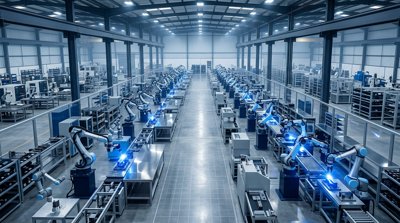
The throughput advantage of a well-engineered integrated line is substantial: optimised material flow, balanced cycle times, and the elimination of manual inter-operation handling all combine to deliver higher output per unit of floor space and lower labour cost per part produced.
In-line inspection integrated throughout the process sequence catches defects at the point of origin rather than at the end of the line, and full traceability across every operation becomes a structural feature of the system rather than something that must be bolted on separately.
The trade-offs are significant: integrated lines require a larger upfront capital commitment, longer commissioning and ramp-up periods (typically three to fourteen months depending on scope and complexity), and considerably less flexibility when product mix or process sequence needs to change.
The higher upfront investment should be evaluated against the ongoing labour and quality savings it enables over the system's operational life — but that analysis belongs in the business case, which is addressed in the next section.
The cell-versus-line decision is the primary architectural axis, but there is a second, related dimension that cuts across it and is worth understanding separately: whether the system processes parts in batches or in continuous flow.
Batch vs. Continuous Processing
In a batch processing system, a fixed quantity of parts completes one operation before the group moves on as a unit — the entire batch finishes deburring before any part moves to the next stage.
In a continuous (through-feed) processing system, parts are loaded at one end and move through each operation in uninterrupted flow, with finished parts offloaded at the other end without waiting for the rest of a batch to catch up.
Batch suits high part variety, operations requiring dwell time (vibratory finishing, plating), heavy deburring of hard-to-machine alloys, and facilities where floor space limits a through-feed layout — batch machines also use less floor space than continuous systems.
Continuous suits high-volume production with stable part geometry, and integrates naturally with downstream coating or assembly lines where flow rate must match — continuous systems are faster and more efficient overall, with no downtime between batches and the ability to spot and correct processing errors in real time.
Critically, the batch/continuous axis is not the same as the cell/line axis: a standalone cell can run batch or continuous processing, and an integrated line can be designed around batch operations that are sequenced automatically.
When a Standalone Cell Is the Right Choice
Several conditions consistently point toward a cell-based architecture as the right starting point.
- Early automation journey: Lower initial investment and contained risk let the organisation learn, build confidence, and demonstrate ROI before committing to larger-scale integration.
- Uncertain or variable volume: Capacity can be adjusted incrementally — idling or adding cells — without stranded investment when demand shifts unpredictably.
- High product mix: Frequent changeover and significant part variation are handled cell-by-cell; new products can be introduced without system-wide reconfiguration.
- Facility layout constraints: Cells fit into available floor space and can be positioned independently, making them practical where a continuous line layout is not feasible.
- Phased capital strategy: A cell can be commissioned and generating return while the business case for further automation is being built from real operational data.
The conditions pointing toward an integrated line are, in most respects, the mirror image — but the logic shifts from flexibility and optionality toward throughput, quality assurance, and labour efficiency.
When an Integrated Line Is the Right Choice
- High-volume stable production: Consistent part geometry and repeatable demand justify the investment in optimised flow; the efficiency gains are only realised at scale.
- Stringent quality requirements: Integrated in-line inspection is the only practical way to achieve 100% coverage at production throughput rates — end-of-line sampling cannot match it.
- Constrained labour availability: Eliminating manual inter-operation handling reduces dependence on operator headcount and skill, which matters most when labour is difficult to source or retain.
- Fixed process sequencing: Where operations must always run in the same order on the same parts, an integrated line enforces that sequence structurally rather than relying on routing discipline.
In practice, most manufacturing environments do not sit cleanly at either end of this spectrum — and the most experienced operators do not try to force them there.
It is common for manufacturers to operate both configurations within the same facility: high-volume commodity parts flow through an integrated line, while custom, low-volume, or geometrically variable parts are handled in standalone cells.
This is not a compromise born of indecision — it is frequently the optimal configuration, one that matches system architecture to actual production behaviour rather than imposing a single approach across a mixed workload.
Many manufacturers begin with standalone cells and integrate selectively as volume grows and process sequences stabilise — the cell-to-line progression is a planned upgrade path, not an admission that the original choice was wrong.
Choosing the right architecture is the starting point — but the detailed engineering decisions within that architecture, covering fixturing, process sequencing, changeover, integration with upstream and downstream operations, and the business case for the investment, are where the real complexity lives, and that is what the next section addresses.
Ready to Spec Your Automated Finishing System?
Whether you are evaluating standalone cells or a fully integrated line, a focused conversation about your parts, volumes, and quality requirements is the fastest way to move from business case to implementable plan.
Integration, Line Planning, and the Business Case
Most automation business cases fail not because the numbers are wrong, but because the integration picture was never properly understood — and when the real costs of commissioning, changeover engineering, and upstream/downstream connectivity emerge post-contract, the payback model no longer holds up. Getting the financial case right starts with getting the integration picture right first.
Integration and Line Planning
Part geometry and variability is the first and most consequential variable in any finishing automation feasibility assessment. Highly consistent prismatic parts — sheet metal blanks, machined components held to tight tolerances — suit dedicated, fixed-path machines precisely because the robot or spindle can follow a predetermined path and trust that the part will always be where the program expects it.
Parts with complex three-dimensional geometry or casting variation cannot be handled this way: the part-to-part differences are large enough that a fixed path will over-process some surfaces and miss others entirely, which is why force-controlled tooling and adaptive sensing exist for this application class.
At the far end of the spectrum, highly variable or mixed incoming parts demand vision-guided path adaptation, where the system measures each part before it moves and adjusts the tool path accordingly — a capability that substantially increases system complexity and cost, and which must be specified from the outset rather than retrofitted.
Fixturing is the variable that experienced integrators watch most closely and that vendor marketing almost never mentions. Parts must be located repeatably enough for the robot to reach every required surface on every cycle — and that repeatability is not a property of the robot, it is a property of the fixture.
Parts that shift under clamping load, flex when the finishing tool contacts them, or present inconsistently due to tolerance stack-up in the fixture itself are among the most common causes of cell underperformance after commissioning. Fixturing deserves engineering time proportional to its importance, which is often 50% or more of whether a cell works as designed.
Process sequencing must be designed into the cell logic, not assumed. Deburring before edge rounding, surface preparation before in-line inspection — these dependencies are obvious in isolation but easy to underspecify when the focus is on individual stations rather than the flow between them.
In high-mix environments, the changeover challenge compounds this significantly. Switching between part families can require different tooling, different force profiles, different robot paths, and different cycle times — all of which must be managed without introducing operator error or excessive downtime. Recipe-driven control systems, quick-change tooling interfaces, and barcode or RFID part identification are the practical mechanisms that make high-mix automation viable rather than theoretical.
The finishing cell also does not exist in isolation. It must receive parts from upstream operations — machining, laser cutting, welding, stamping — and hand them off to downstream operations including coating, assembly, inspection, and packaging. Each of those handoffs carries engineering requirements that are easy to underestimate at the planning stage.
Conveyor compatibility, line speed synchronisation, and the handshake protocols between the finishing cell's controls and the broader production line are where the most expensive post-commissioning problems tend to originate. Integration with MES or ERP systems for production tracking, scheduling, and traceability adds another layer of complexity that must be scoped explicitly — not left as a late-stage assumption.
The following variables represent the integration checklist that any line plan must address before capital commitment. Each one has cost implications, and any that are underspecified will surface as change orders or performance shortfalls after installation.
- Part geometry and variability: Determines whether fixed-path, force-adaptive, or vision-guided programming is required — the single largest driver of system complexity.
- Fixturing and part presentation: Parts must locate repeatably on every cycle. Fixture design is frequently the difference between a cell that performs and one that doesn't.
- Process sequencing logic: Operation order must be engineered into the control system. Dependencies between stations cannot be assumed or resolved informally.
- Changeover and high-mix handling: Recipe-driven controls, quick-change tooling, and part identification systems are required for high-mix production to be economically viable.
- Upstream and downstream connectivity: Conveyor compatibility, line speed matching, and handshake protocols with adjacent operations must be specified before commissioning, not after.
- MES and ERP integration: Controls integration for production tracking, scheduling, and traceability must be scoped explicitly — it is not a standard inclusion.
Every item on that list has a cost. The more of them that require bespoke engineering — custom fixtures, vision-guided adaptation, multi-system controls integration — the higher the total investment. This is precisely why the integration picture must be established before the business case is built: the cost of the investment is a direct function of integration complexity, and a model built without that clarity will be wrong.
Building the Business Case
The correct evaluative frame for automated metal finishing investment is total cost of ownership, not upfront capital. The ongoing cost structure of automated finishing is fundamentally different from manual finishing, and comparing them on capital alone produces a misleading picture in both directions.
A complete TCO model must capture: equipment cost, integration engineering and commissioning, tooling and consumables, controls and software, programming and ramp-up time, and ongoing maintenance — which typically runs in the range of 3–5% of equipment cost per year. A business case that omits integration engineering and ramp-up will be wrong in a way that destroys credibility the moment actual invoices arrive.
Labour savings are usually the most visible ROI component, but they are also the most commonly miscalculated. The figure that belongs in the business case is not the base hourly wage — it is the fully burdened labour cost, which includes employer contributions, holiday and sick pay, PPE, training, recruitment, and supervision overhead.
Fully burdened labour cost is typically 30–50% above the base wage rate, meaning a business case built on base rates alone will systematically understate the true saving — and when finance challenges the model, the gap will be visible immediately.
Displacement assumptions matter equally. A cell that automates the finishing operation but still requires an operator for loading and unloading may realistically eliminate 1.5 FTEs rather than 2.0. Overclaiming labour displacement is one of the most common errors in automation business cases, and it is one of the first things a sceptical finance team will probe.
Fully burdened labour cost — which includes NI contributions, holiday pay, sick pay, PPE, training, and supervision — runs 30–50% above the base hourly rate. A business case built on base rates alone systematically understates the true labour saving and will not survive scrutiny from finance.
Scrap and rework reduction is the second ROI component, and unlike labour savings it can be quantified directly from historical data. The calculation is straightforward: current scrap rate multiplied by average part value multiplied by annual volume gives a concrete monetary figure that finance can evaluate and audit against actual outcomes.
The third component is throughput gain. Consistent cycle times and improved overall equipment effectiveness translate to more output from the same floor space — which either increases revenue capacity or defers capital investment in facility expansion. Both outcomes have real monetary value, and both should be expressed as mechanisms in the business case rather than asserted as general benefits.
Payback period is the metric that most executive teams reach for first. For well-specified, high-volume applications, 12–24 months is a realistic range; mid-volume or high-mix applications typically run 18–30 months, reflecting the higher integration complexity and longer ramp-up time associated with those environments.
Presenting a single payback figure — even a realistic one — is a credibility risk. Finance teams and operations leadership have seen optimistic automation projections fail to materialise, and a single-scenario model signals that the analyst has not stress-tested the assumptions. The more effective approach is to present three scenarios: conservative, expected, and optimistic, each with transparent assumptions about volume, displacement, scrap rate, and ramp-up time.
The three-scenario structure does more than protect against challenge — it actively builds confidence, because it demonstrates that the analyst has already considered the downside and the investment still holds up. That signal is often the difference between a business case that gets approved and one that gets sent back for more work.
When payback extends beyond 24 months, payback period alone becomes an inadequate metric, because it does not capture the value of returns that arrive after the payback point. In those cases, NPV or IRR analysis is the more appropriate framing — it accounts for the full duration of the return stream and gives leadership a more complete picture of long-term value.
The quality and traceability data generated by an automated finishing system is not just an input to the ROI model — it is also the operational record that regulatory compliance and customer quality audits increasingly require. How automated systems build, log, and surface that data is the subject of the next section.
Process Control, Quality Assurance, and Regulatory Compliance
In a well-specified automated finishing cell, conformance is not inspected into the product — it is an output of process design. Programmed force, path, speed, and tooling deliver the same result on every cycle, regardless of who is operating the machine. That is a fundamentally different quality paradigm from manual finishing, where the process varies with the operator and quality control is necessarily reactive.
Building Quality Into the Process
In-process monitoring is the first layer of quality assurance: watching the process itself, in real time, as each part runs.
Force and torque sensors read contact conditions continuously throughout the finishing cycle. When a spindle load or force profile deviates from the validated baseline, it signals a condition that would otherwise become a defect — a tool worn beyond threshold, a part sitting fractionally off-position in the fixture, or an anomalous feature on an individual casting.
The operational value is timing: the deviation is caught in-cycle, not after the part has been finished, moved to inspection, and potentially built into an assembly.
In-line inspection is distinct from in-process monitoring — it verifies the output rather than watching the process. Machine vision systems check burr removal and surface condition at each critical edge; laser profilometry measures the actual edge radius and surface profile against the CAD-defined specification.
The critical advantage is coverage: automated in-line inspection achieves 100% part inspection at production rates, whereas manual inspection is statistically sampled and inherently misses a proportion of non-conforming parts.
Machine vision and laser profilometry serve complementary roles. Vision provides high-speed, full-surface coverage for burr detection and cosmetic defect classification. Profilometry delivers quantitative dimensional measurement — edge radius, surface roughness — traceable to specification. Production systems typically combine both: vision for 100% screening, profilometry for quantitative verification on flagged or critical parts.
Data Logging and Part-Level Traceability
Every parameter an automated finishing cell generates — force profile, spindle load, cycle time, vision inspection result — can be linked to a unique part identifier via barcode, DataMatrix code, or RFID scan at infeed. The result is a complete, serialised production record for every part that passes through the cell.
That record enables root cause analysis when a non-conformance surfaces downstream or in service, supports customer quality audits where the manufacturer must demonstrate that every part was processed to specification, and provides the trend data needed to detect process parameter drift before it produces defects.
The process data an automated finishing cell generates as a by-product of normal operation — force profiles, cycle times, spindle loads, inspection results, all tied to individual part serial numbers — is precisely the traceability record that AS9100, Nadcap, and IATF 16949 audits require. Manufacturers who think of automation primarily as a throughput tool often overlook this: the compliance infrastructure comes built in.
Regulatory Frameworks Governing Metal Finishing
Automated finishing operations sit within a defined regulatory landscape. The frameworks most relevant to manufacturers in aerospace, automotive, and chemical process sectors are:
- OSHA 29 CFR 1910.1026: Hexavalent chromium standard for general industry. Sets the PEL at 5 µg/m³ (8-hr TWA) and action level at 2.5 µg/m³.
- EPA 40 CFR Part 433: Metal Finishing Effluent Guidelines. Governs wastewater discharge from six primary operations including electroplating, anodising, and chemical etching.
- AS9100 / Nadcap AC7108: Aerospace quality management and special process accreditation. Requires documented, auditable process controls and full part traceability.
- IATF 16949 / CQI-11 / CQI-12: Automotive QMS standard and AIAG process-specific assessments for plating and coating. Require in-process monitoring, control plans, and corrective action evidence.
Each of these frameworks has distinct operational implications for how a finishing system must be designed, documented, and audited. Manufacturers operating in regulated supply chains should engage qualified compliance professionals for guidance specific to their operations.
OSHA Hexavalent Chromium: Exposure and Engineering Controls
OSHA's Cr(VI) standard (29 CFR 1910.1026) establishes a permissible exposure limit of 5 µg/m³ as an 8-hour time-weighted average. The action level is set at 2.5 µg/m³ — the threshold at which periodic monitoring and medical surveillance obligations are triggered.
Engineering and work practice controls are the primary means of compliance: the standard requires employers to use feasible engineering controls to reduce and maintain exposures at or below the PEL before relying on respiratory protection.
Automation changes the exposure picture directly. Removing operators from the process environment reduces or eliminates personal Cr(VI) exposure — which is not just a safety benefit but a compliance mechanism that simplifies monitoring obligations and reduces the engineering control burden for occupied workspaces.
EPA Metal Finishing Effluent Guidelines
The EPA's Metal Finishing Effluent Guidelines (40 CFR Part 433), promulgated in 1983, govern wastewater discharge from facilities performing any of six primary operations: electroplating, electroless plating, anodising, coating (phosphating, chromating, and colouring), chemical etching and milling, and printed circuit board manufacture. Where any of these six operations is present, discharges from 40 additional listed operations at the same facility are also covered.
Automated process control supports discharge compliance through recipe-driven chemistry dosing that maintains bath concentrations within specification, and through automated monitoring that can trigger alarms or process holds when parameters drift toward out-of-limit conditions.
Automation does not eliminate discharge compliance obligations — but it makes compliance more consistent and more auditable, with documented parameter records that demonstrate control over time.
Aerospace Quality: AS9100 and Nadcap Accreditation
For aerospace finishing operations, the quality management framework is AS9100 — built on ISO 9001 with aerospace-specific additions covering risk management, configuration control, and first article inspection. Special processes, including chemical processing and plating, typically require Nadcap accreditation by OEM customer flow-down.
The relevant Nadcap commodity for chemical finishing is AC7108, which covers plating, anodising, conversion coatings, etching, and related chemical processing operations. Accreditation requires audited conformance to process specifications, documented process controls, traceability of materials and process parameters, and periodic re-accreditation audits conducted through the PRI eAuditNet system.
What an automated finishing cell provides is exactly what an AC7108 audit will examine: every parameter logged, every part traceable, every deviation recorded. The data architecture that makes the cell run also constitutes the objective evidence the accreditation audit requires.
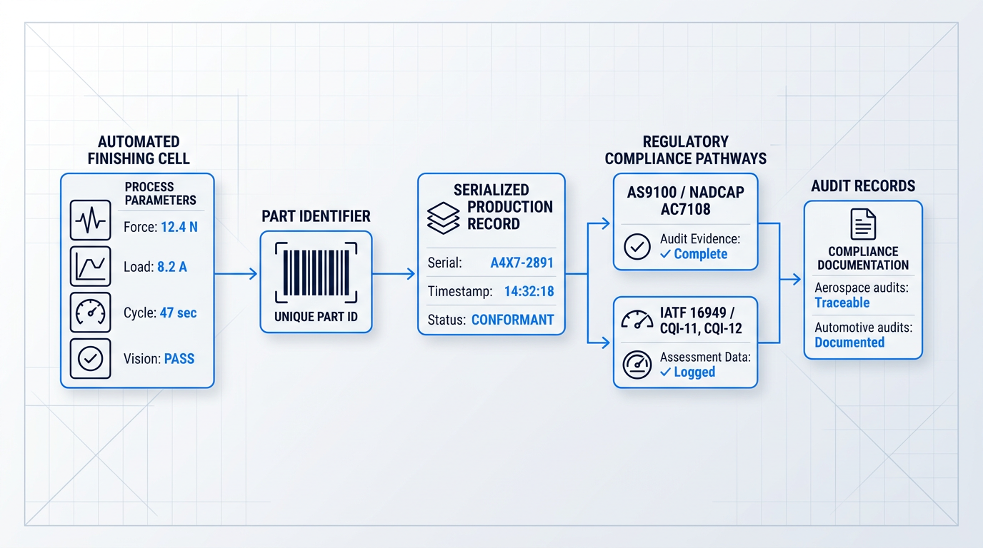
The same data architecture that satisfies Nadcap AC7108 audit requirements translates directly to the automotive sector, where a parallel but distinct set of process-specific obligations applies.
Automotive Quality: IATF 16949 and CQI Assessments
Automotive suppliers performing finishing operations must hold IATF 16949 certification — the sector-specific quality management system standard that governs the automotive supply chain. For plating operations, the applicable AIAG process-specific assessment is CQI-11; for coating operations, it is CQI-12.
CQI assessments are used in supplier audits under IATF 16949 and require objective evidence of documented process parameters, in-process monitoring, calibrated test equipment, and functioning corrective action systems. OEM customer-specific requirements — including those from GM and FCA — mandate that suppliers conduct these assessments annually and upload results to the relevant supplier certification management system.
The process data an automated cell generates naturally — logged parameters, in-cycle monitoring results, per-part inspection records — is precisely what a CQI-11 or CQI-12 assessment auditor will ask to see. Facilities running manual processes must reconstruct this evidence; automated facilities generate it as a by-product of production.
The Regulatory Direction of Travel
The regulatory environment governing chemical finishing is tightening on multiple fronts simultaneously. In the EU, REACH Annex XIV subjects hexavalent chromium compounds to authorisation requirements — ECHA has been mandated to prepare a restriction proposal covering Cr(VI) substances currently on the authorisation list, with electroplating identified as one of the primary uses in scope. In the US, the EPA is advancing rulemaking to revise the Metal Finishing Effluent Guidelines (40 CFR Part 433) to address PFAS discharges from chromium finishing facilities, driven by evidence that approximately half of chromium electroplating facilities have used PFAS-based fume suppressants.
OEM mandates are reinforcing these regulatory signals. Automotive OEMs are engaged in collaborative discussions with the surface finishing industry and regulators on voluntary reduction of PFAS and hexavalent chromium in the supply chain, while aerospace programmes are increasingly specifying non-chromate alternative finishes across both military and commercial applications.
The direction is clear: manufacturers investing in process automation today are also positioning for the chemistry transitions these regulations will require — automated systems are more readily adapted to alternative chemistries, and their documented process control infrastructure supports the compliance demonstrations that regulators and customers will increasingly demand. These pressures are simultaneously accelerating interest in alternative surface treatment methods that eliminate chemical handling entirely.
Automated Laser Cleaning in Metal Finishing
The regulatory pressures covered in the previous section — OSHA limits on hexavalent chromium, EPA effluent guidelines, REACH restrictions — share a common root cause: cleaning chemistry. Laser cleaning sidesteps that root cause entirely, not by managing chemical waste more carefully, but by eliminating it from the process altogether.
Surface preparation is a prerequisite for everything downstream. Oxides, mill scale, rust, weld discolouration, release agents, and adhesive residues left on a part before coating, bonding, or plating will undermine the quality of those processes regardless of how well the subsequent steps are executed.
The cleaning step is where that contamination is removed — and the method chosen determines not just cleanliness, but waste liability, consumable cost, substrate integrity, and throughput consistency.
How Laser Cleaning Works
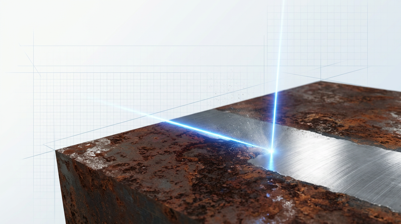
The mechanism is ablation: a pulsed fibre laser delivers energy to the part surface, vaporising or detaching the contaminant layer while leaving the base material essentially untouched.
The beam is tuned to the absorption characteristics of the contaminant rather than the substrate, so the energy stops where the contamination ends — substrate loss is minimal, which directly reduces rework from over-cleaning or surface distortion.
Compared to chemical stripping, laser cleaning generates no process waste, requires no handling of hazardous substances, and produces no effluent requiring treatment or disposal. Compared to abrasive blasting, it introduces no media contamination, causes far less substrate impact, and eliminates the ongoing cost of consumable replenishment.
The total cost of ownership framing matters here: zero consumables, less downtime, and less rework compound into a fundamentally different ongoing cost structure — one that looks increasingly attractive as chemical compliance costs rise.
Handheld laser cleaning systems exist and are useful for maintenance and repair contexts, but for production finishing, the step-change comes from automation.
In a robotic laser cleaning cell, the laser head is carried on an articulated arm that follows a programmed path across the part surface — reaching the angles, recesses, and contours of complex 3D geometries that a handheld operator would struggle to address consistently.
Every cycle delivers cleaning to the same standard, independent of operator skill or fatigue. That is the same argument this guide has made throughout for automated finishing broadly: automation is the bridge between a capable technology and a production-grade process.
AutoLASE: Our Automated Laser Cleaning System
Our automated laser cleaning system, AutoLASE by Woodrow Scientific Limited, illustrates what a production-ready automated laser cleaning cell looks like in practice — and where the technology has reached in terms of ease of operation.
The defining characteristic of AutoLASE is not that it automates the cleaning path — it is how effortlessly it does so. Load the part, and the system's machine vision scans it, builds a 3D map, and generates the cleaning path automatically, with no manual programming, no path-setting, and no knowledge of part geometry required.
That means anyone on the production floor can load a part and run a cleaning cycle — no specialist programming skills, no CAD knowledge, no setup time between different part types.
A second differentiator is the optional Reduced Hazard Zone (RHZ) configuration. AutoLASE can be upgraded with WSL's eye-safe technology, allowing it to operate with no enclosure at all. This capability is provided exclusively by WSL worldwide — no other supplier offers enclosure-free automated laser cleaning.
AutoLASE's optional Reduced Hazard Zone (RHZ) upgrade enables fully automated laser cleaning with no enclosure required — a capability provided exclusively by Woodrow Scientific Limited. No other supplier worldwide offers this configuration.
On price, AutoLASE is the European cost leader among comparable industrial laser cleaning machines — the most competitively priced option in its class, achieved through WSL's technological and operational efficiencies rather than any compromise on quality or specification.
The company behind the system matters too. Woodrow Scientific Limited is the only UK-based laser cleaning manufacturer — designing, building, servicing, and improving its machines entirely in-house. A notable proportion of suppliers in this market are resellers or importers rebadging third-party equipment, which means limited engineering capability, slower support, and no real ability to develop the product. WSL's in-house model is the direct alternative to that.
Beyond those differentiators, AutoLASE carries CE and UKCA certification, with first-class laser cleaning safety and operation training available. It can integrate with a customer's existing robots or be supplied as a complete custom cell, and WSL offers bespoke engineering and integration support — organisations with specific requirements are encouraged to get in touch to discuss what is possible.
The system's operational breadth makes it relevant across the full range of cleaning tasks a metal finishing operation encounters, not just a single contaminant type or substrate.
- Metals cleaned: Steel, carbon steel, aluminium alloys, cast iron, copper, brass, bronze, titanium, and galvanised surfaces.
- Contaminants removed: Rust, mill scale, oxides, paint, powder coating, weld discolouration, release agents, adhesive residues, oil, grease, and more.
- Tunable power: 0–100% power adjustment across a 300W fibre laser — from light surface oxides through to thick coatings, in one cell.
- Flexible reach: Articulated robotic arm with delivery cable up to 50m, reaching complex 3D geometries and tight contours consistently.
- No utilities required: Air-cooled with no chiller, coolant circuit, water supply, or chemical handling infrastructure needed.
That combination — wide substrate compatibility, full contaminant range, and continuously tunable power — means a single system can handle the variety of cleaning tasks that would otherwise require multiple process stages or specialist equipment.
From a compliance standpoint, the process profile is straightforward: no chemical waste, no abrasive media disposal, no hazardous substance exposure from cleaning chemistry. The OSHA, EPA, and REACH pressures that make chemical-based cleaning increasingly costly to operate simply do not apply to a laser-based process.
The optional RHZ configuration adds a further practical advantage in space-constrained facilities: no enclosure means no footprint penalty, no installation cost for safety infrastructure, and no structural modifications to the production floor.
On total cost of ownership, the picture is consistent with the broader automation case this guide has built: no consumables to replenish, minimal substrate damage reducing rework, and less process downtime. AutoLASE's position as the European cost leader means that even the machine-to-machine price comparison resolves favourably — making the TCO argument stronger still.
With that, the guide has covered the full arc of automated metal finishing — from process types and equipment through system architectures, integration planning, quality and compliance, and now clean-technology alternatives. The conclusion draws these threads together and points toward practical next steps.
See Laser Cleaning in an Automated Finishing Context
No chemistry, no effluent, no compliance overhead. Explore our laser cleaning machines built for integration into automated metal finishing workflows.
Conclusion
Bringing it together: making the case for automated finishing
Automated metal finishing is not a single technology with a single answer — it is a family of processes, equipment types, and system architectures, and the right fit depends entirely on your specific parts, volumes, and quality requirements.
That means the evaluation belongs on the full cost picture, not the capital line alone.
The practical next step is identifying which of your processes are genuine candidates, then engaging with integrators or suppliers who can model the real-world numbers against your situation.
Frequently Asked Questions About Automated Metal Finishing
Specific questions about robotic finishing systems, equipment, compliance, and process selection — answered directly.
Parts best suited to robotic finishing share three characteristics: consistent geometry, sufficient production volume to justify the programming investment, and quality requirements that manual finishing cannot reliably meet cycle to cycle. If your parts tick all three, automation is worth evaluating seriously. Complex 3D geometries are not automatically excluded — systems equipped with force control and vision-guided path adaptation can handle curved surfaces and compound profiles. Where parts vary significantly in incoming dimensions (mixed castings, wide tolerance spreads), adaptive sensing is needed to manage that variation rather than a fixed programmed path. The harder cases are genuinely low-volume, high-mix environments where frequent changeover erodes the economics of programming investment.
Force control allows the robot to maintain constant contact pressure regardless of part-to-part dimensional variation or tool wear — adapting in real time rather than executing a rigid pre-programmed path. That adaptive response is what delivers consistent surface finish across an entire production run, not just on the first part. Without force control, a robot is essentially a fixed path-follower. Any variation in casting dimensions, incoming tolerances, or gradual tool wear feeds directly into the output as inconsistent finish quality — the same problem manual finishing has, just faster. Force control closes that feedback loop, making the process self-correcting within defined parameters.
For well-specified, high-volume applications, payback typically falls in the 12–24 month range. Mid-volume or high-mix applications generally run 18–30 months, depending on changeover frequency and programming complexity. The key variables are fully burdened labour cost (benefits, overhead, and supervision — not just the base hourly rate), current scrap and rework rates, and realistic labour displacement assumptions. A cell that eliminates 1.5 FTEs rather than 2.0 because a human operator is still needed for loading changes the calculation meaningfully. Where payback extends beyond 24 months, simple payback framing becomes less useful — NPV or IRR analysis gives a clearer picture of long-term value. Consult your finance team or an automation integrator to model your specific scenario accurately.
A standalone finishing cell is a self-contained workstation: parts are loaded and unloaded manually between operations. Lower upfront investment, faster commissioning, and more flexibility for product mix changes make it a practical starting point for many manufacturers. An integrated production line connects multiple finishing operations in continuous automated flow — higher throughput, lower labour cost per unit, and tighter integrated quality control, but at significantly higher capital cost and with less flexibility when product mix changes. In practice, many manufacturers run a hybrid: high-volume commodity parts through integrated lines, with standalone cells handling custom work, lower volumes, or product families that rotate frequently.
Requirements vary significantly by process. Chemical finishing operations discharging to waterways or municipal systems are subject to the EPA Metal Finishing Effluent Guidelines (40 CFR Part 433), which set limits on metals, cyanide, and other pollutants in wastewater. Operations using hexavalent chromium must comply with OSHA's Cr(VI) standard (29 CFR 1910.1026), which sets a permissible exposure limit of 5 µg/m³ as an 8-hour TWA. Sector-specific requirements add further layers: aerospace suppliers typically need AS9100 certification and Nadcap accreditation for special processes; automotive suppliers must meet IATF 16949 requirements, including CQI assessments such as CQI-11 for plating and CQI-12 for coating. This answer is for awareness only — consult the relevant regulatory bodies or a qualified compliance professional for guidance specific to your operations.
Yes. Automated laser cleaning is used as a surface preparation step within finishing workflows, removing oxides, mill scale, rust, paint, weld discolouration, and surface contamination from metal parts before bonding, coating, plating, or further mechanical finishing. It is chemical-free and produces no consumable waste — no chemistry to dispose of, no abrasive media, no wastewater generated by the cleaning step itself. That profile is directly relevant to the regulatory pressures that chemical finishing operations face under EPA effluent guidelines and OSHA exposure limits. Laser cleaning integrates readily into automated lines and cells, with the laser head mountable on a robot arm or gantry for consistent, programmable coverage.
The three main families are mechanical finishing, mass and vibratory finishing, and wet-process finishing. Mechanical finishing covers deburring, edge rounding, grinding, polishing, and surface smoothing — typically applied to individual parts using robotic or CNC-controlled tooling. Mass and vibratory finishing treats parts in bulk through tumbling, drag finishing, or vibratory bowl systems, making it well-suited to high volumes of smaller components. Wet-process finishing encompasses electroplating, anodising, electropolishing, passivation, and chemical conversion coatings, where the part is processed in a chemical bath to alter its surface properties or apply a functional layer. Cutting across all three is surface preparation and cleaning — parts generally need to be free of contamination before any finishing process can deliver its intended result consistently.