

Introduction
If you work in aerospace engineering, MRO, or procurement, you already know that cleaning sits at the centre of component performance, airworthiness, and programme compliance.
What is harder to navigate is the range of available approaches, each with its own strengths, constraints, and operational consequences.
This guide covers the full landscape of aerospace cleaning without advocating for any single method — the aim is an accurate picture of the options, not a steer toward one.
It moves from the technology landscape through compliance and verification, environmental and safety trade-offs, operational efficiency, and downstream process compatibility, closing with a practical framework for method selection.
The focus throughout is on why choices matter and what the real-world consequences of those choices are.
TL;DR
No single aerospace cleaning method is universally optimal. The right choice is always a product of matching contamination type, substrate, geometry, cleanliness target, downstream process, and operational context — and getting that match wrong carries measurable consequences for performance, compliance, and cost.
This guide gives you the framework to make that match with confidence.
This article covers:

Aerospace cleaning technologies compared
Cleanliness standards, verification, and compliance
Environmental and worker safety chemistry trade-offs
Throughput, automation, and operational efficiency
Compatibility with bonding, coating, sealing, and NDT
Decision framework for selecting the right method
What is aerospace cleaning?
In most industries, a component that looks clean is clean enough. In aerospace, that assumption can cause system failure.
Aerospace cleaning is the specialised removal of contamination from aerospace components, assemblies, and surfaces using precision methods, chemistries, and equipment to meet stringent, formally defined performance and safety requirements.
What separates aerospace cleaning from general industrial cleaning is the direct, quantifiable link between surface cleanliness and component performance. Contamination in a hydraulic system is not a cosmetic issue: even sub-visible particulate can cause valve wear, seal damage, and system malfunction. Molecular films on bonding surfaces are a primary cause of adhesive bond failure in composite and metal structures. On thermal control surfaces and optical components, residue films alter emissivity and cause optical obscuration and absorption losses.
The aerospace industry formalises these risks through contamination control frameworks that categorise contamination by type and treat its performance consequences as engineering variables to be specified, measured, and controlled.
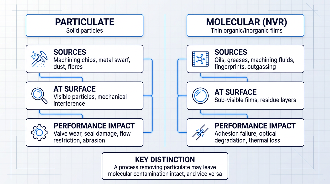
Two primary contamination categories define the problem space, each with distinct sources, failure modes, and cleaning requirements.
- Particulate contamination: Solid particles — dust, fibres, metal swarf, machining chips. Causes mechanical interference, abrasion, valve wear, and flow restriction. Sub-visible particles remain damaging.
- Molecular contamination: Thin films of organic or inorganic material — oils, greases, machining fluids, fingerprint residues, outgassing products. Causes adhesion failure, optical degradation, and thermal performance loss.
The distinction between these two categories is not academic. A cleaning process that effectively removes particulate contamination may leave molecular contamination — also called non-volatile residue (NVR) — entirely intact, and vice versa.
Selecting a method without accounting for both contamination types is a common source of cleaning process failure, and it is why this distinction recurs throughout the technology, standards, and verification sections of this guide.
Cleanliness in aerospace is not a binary state. The industry uses formally defined cleanliness classes — structured levels that specify the maximum allowable contamination for a given component or application.
The required class is determined by the component's function and the sensitivity of its downstream use: a hydraulic servo valve operates to a far more stringent cleanliness target than a structural airframe panel, and an optical sensor demands a different specification entirely from a structural fastener. This spectrum of requirements is why no single cleaning approach can be universally applied across an aerospace programme.
In aerospace, contamination has documented, measurable consequences for component function and system safety. Cleanliness levels are formally defined, verified against those definitions, and recorded — because the performance stakes make ambiguity unacceptable.
These principles apply across two distinct operational contexts. Manufacturing and assembly cleaning takes place in controlled environments — often cleanrooms or dedicated precision cleaning areas — where contamination is process-derived: machining fluids, handling residues, and process chemicals on new components.
MRO (maintenance, repair and overhaul) cleaning addresses components that have been in service, carrying operational contamination such as carbon deposits, corrosion products, hydraulic fluid, and environmental soiling. The contamination categories are the same; the drivers, constraints, and compatible methods differ significantly.
With the contamination problem defined and categorised, the next step is understanding the range of methods the aerospace industry uses to address it — and how each maps to the contamination types and cleanliness levels described here.
Aerospace cleaning technologies: the landscape
No single cleaning method works for every aerospace application — and the gap between a well-matched method and a poorly-matched one is not marginal. The six principal aerospace cleaning technologies differ fundamentally in their mechanisms, their effectiveness against different contamination types, and the constraints they impose on the process. Understanding each on its own terms is the prerequisite for any meaningful selection decision.
Ultrasonic cleaning
Ultrasonic cleaning works by propagating acoustic energy through a liquid bath to generate cavitation — the rapid formation and violent collapse of microscopic bubbles at the component surface, releasing localised pressure and temperature that dislodges contamination.
Frequency selection is a critical process variable. At lower frequencies (20–40 kHz), cavitation bubbles are larger and more energetic, suited to heavier soils and robust substrates. At higher frequencies (60–80 kHz and above), bubbles are smaller and gentler, making them appropriate for delicate surfaces, fine geometries, and submicron particle removal — a distinction that matters considerably given the range of substrates and surface finishes found across aerospace applications.
The geometric access advantage of ultrasonic cleaning is significant for aerospace work: cavitation reaches blind holes, internal passages, and complex three-dimensional geometries that manual brushing or spray methods cannot reliably access, making it well-suited to hydraulic components, fuel system parts, and precision machined assemblies.
Characteristic constraints include the requirement for liquid immersion — not all components can be safely submerged — along with drying requirements after cleaning, the risk of cavitation damage on very delicate surfaces if frequency is incorrectly set, and the need to verify compatibility between the cleaning fluid chemistry and the substrate material.
Vapour degreasing
Vapour degreasing uses a closed-loop solvent system: components are lowered into a chamber where solvent vapour condenses on the cooler part surface, dissolving non-polar organic contamination, then drains back to a sump for re-distillation and reuse — cleaning and drying occur in a single cycle with no separate rinse stage required.
The method is particularly effective against non-polar molecular contamination — machining oils, cutting fluids, waxes, and corrosion inhibitors — which are among the most prevalent soil types in aerospace manufacturing environments.
Vapour degreasing integrates readily into production lines: cycle times are short, the process footprint is compact, and modern cleaning fluids are formulated with low surface tension and very low viscosity, allowing penetration into tight spaces including blind holes and closely stacked parts.
The evolution of cleaning fluid chemistry is an active area of development. The industry has moved away from older chlorinated solvents toward lower-VOC, lower-HAP formulations in response to environmental regulation — but this remains a live compliance landscape rather than a settled one. Characteristic constraints include limited effectiveness against polar contaminants such as salts and ionic residues, and the ongoing requirement to verify that the chosen fluid is compatible with the substrate.
Aqueous cleaning
Aqueous cleaning combines water-based detergent chemistry with mechanical action — spray, immersion, or ultrasonic agitation — to remove polar contaminants including salts, emulsion residues, oxidation products, and ionic soils that solvent-based methods do not address effectively.
The process carries meaningful operational overhead: heating water and drying parts consumes substantial energy, drying requirements extend cycle time, and wastewater must be treated before disposal.
A particular concern for aerospace applications is moisture entrapment in blind holes, complex geometries, or assemblies with trapped volumes — residual moisture can initiate corrosion or interfere with downstream processes, and ensuring complete drying on intricate components is a genuine engineering challenge.
Aqueous systems avoid organic solvent exposure, which is a meaningful advantage in some regulatory and worker-safety contexts, but they introduce their own environmental and operational overhead in the form of energy consumption and wastewater management — a trade-off that will be examined in more depth later in this guide.
CO₂ snow cleaning
CO₂ snow cleaning works by expanding liquid CO₂ through a nozzle to produce a stream of solid CO₂ particles that impinge on the surface, dislodging contamination through a combination of kinetic energy, mild thermal effect, and sublimation — the CO₂ converts directly to gas on contact, leaving no residue of any kind.
The method is dry, residue-free, and non-abrasive: it does not wet the surface, does not introduce chemical residue, and does not abrade the substrate, making it well-suited to sensitive optical components, electronic assemblies, and precision surfaces where liquid contact or chemical exposure is not acceptable.
The primary constraint is cleaning scope: CO₂ snow is effective against light surface contamination — particulate, molecular films, and light organic residue — but is not suited to heavy soils, thick coatings, or tenacious deposits. It also carries a line-of-sight limitation, meaning internal passages and blind holes cannot be reached.
Dry ice blasting
Dry ice blasting removes contamination through three simultaneous mechanisms: kinetic impact as solid CO₂ pellets accelerated in a compressed air stream strike the surface; thermal shock as the pellets at approximately −78.9°C rapidly cool and embrittle the contamination layer, causing it to fracture and delaminate; and volumetric gas expansion as the CO₂ sublimates on impact, expanding up to 800 times its solid volume and lifting the loosened contamination away from the surface.
The process is non-abrasive — CO₂ pellets are softer than most substrate materials — produces no secondary waste as the CO₂ sublimates completely, and uses no chemistry and no water.
Aerospace applications include composite tool and mould cleaning, adhesive removal, compressor blade cleaning, and MRO cleaning of engine components. Rolls-Royce granted a formal approval letter for the use of dry ice cleaning on aircraft turbine titanium compressor drum assemblies following testing that confirmed minimal effect on material microstructure — a specific, named validation that speaks to the method's suitability for precision aerospace hardware.
Characteristic constraints include the logistics of maintaining a supply of dry ice pellets, the need for a dry and cool compressed air supply, noise levels during operation, the line-of-sight limitation that prevents access to complex internal geometries, and the requirement to collect and dispose of the removed contamination — unlike CO₂ snow, the contaminant itself is not sublimed away.
Laser cleaning
Laser cleaning works through ablation: a pulsed laser beam is absorbed by the contamination layer, which reaches its ablation threshold and is vaporised or sublimed, while the underlying substrate — which absorbs less energy at the chosen wavelength — remains largely unaffected.
The process is selectively tunable: laser power can be adjusted across a wide range, allowing the same system to address light oxide films at lower power settings and thick coatings or heavier contamination at higher settings, with parameters optimised for specific contamination and substrate combinations.
Laser cleaning requires no consumables, no solvents, no abrasives, and no water, which eliminates chemical waste streams and simplifies regulatory compliance — a characteristic that distinguishes it from the wet and chemical-based methods in this landscape.
Aerospace adoption is well-established across both MRO and manufacturing contexts. The U.S. Navy's Fleet Readiness Center East (FRCE) has demonstrated laser ablation technology for removing corrosion and hazardous coatings from aircraft components, with representatives successfully stripping paint from a large aircraft engine can during a formal technology evaluation. On the manufacturing side, the F-35 programme has put into production an Automated Structure Laser Cleaner system on the wing line, using laser ablation to remove primers and protective coatings to prepare surfaces for nutplate bonding — replacing manual sanding and solvent wiping. Laser cleaning is also used in composites manufacturing to remove resins, release agents, and oxides from production molds and to prepare CFRP panels for adhesive bonding.
Characteristic constraints include the capital cost of laser equipment, the line-of-sight requirement that prevents access to internal passages, the need for trained operators and appropriate laser safety controls, and the fact that cleaning speed across large surface areas may be lower than blasting-based methods.
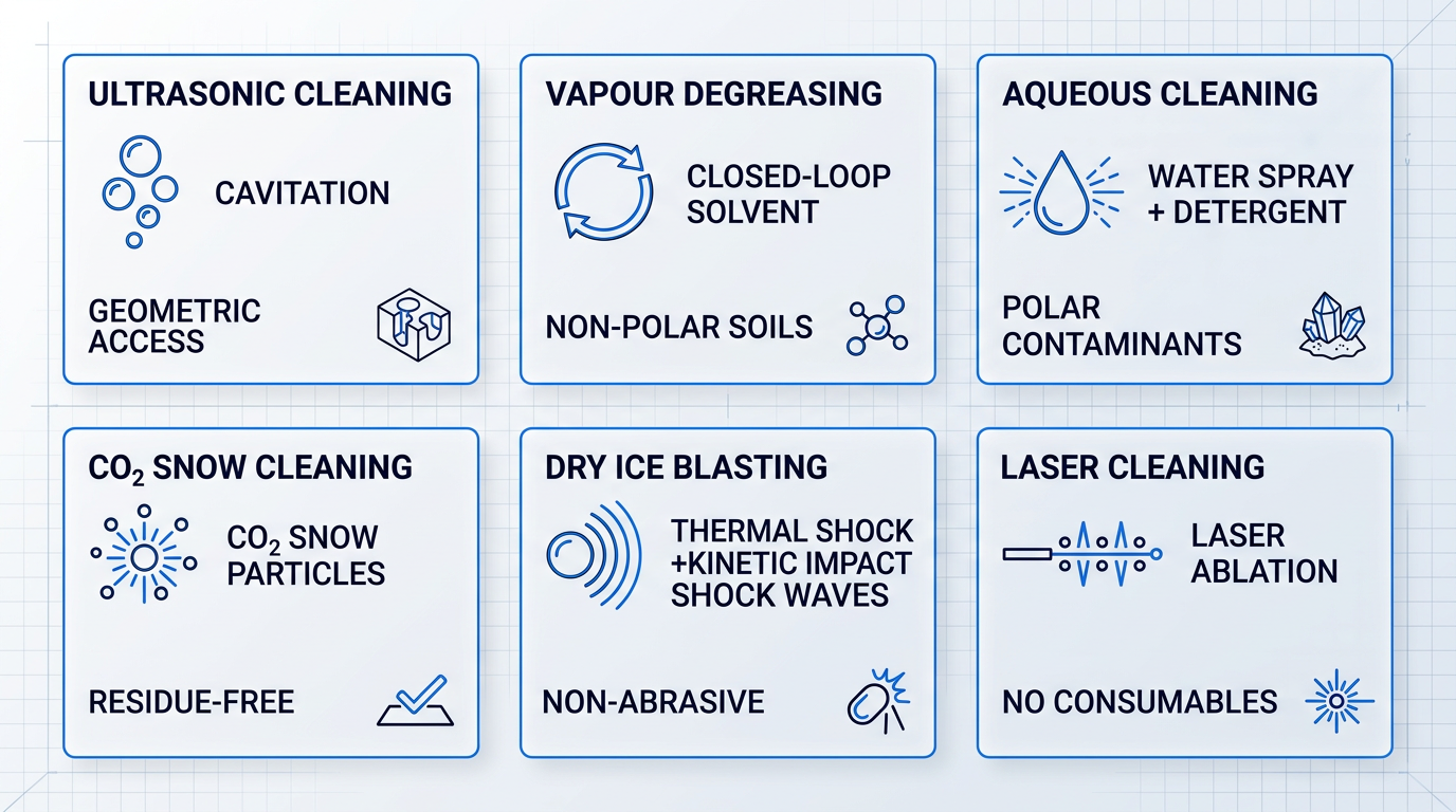
Across all six methods, the right choice for any given aerospace application is determined by a specific combination of factors: the contamination type present (polar, non-polar, particulate, or mixed), the substrate material and its tolerances, component geometry and internal access requirements, the required cleanliness target, throughput and cycle time constraints, and the applicable environmental and regulatory context.
Each of the six principal aerospace cleaning technologies has a contamination profile, geometry, and operational context where it genuinely outperforms the others — and a set of conditions where it is the wrong choice. Method selection is always a function of the specific application, not a general ranking.
With the technology landscape established, the next step is grounding these methods in the specific characteristics of aerospace components and assemblies — because it is the geometry, material, and service context of the part being cleaned that ultimately shapes which methods are viable and which are not.
Aerospace components and their cleaning challenges
Walk through any aerospace MRO facility and the cleaning challenge looks entirely different from one workstation to the next. A turbine blade presents a geometry and deposit problem. A hydraulic line presents a particulate contamination problem. An avionics board presents a residue chemistry problem. The component, not the cleaning technology, is where the decision must start — because the geometry, base material, contamination type, and downstream use of each assembly combine to define a requirement that no single method can satisfy across the board.
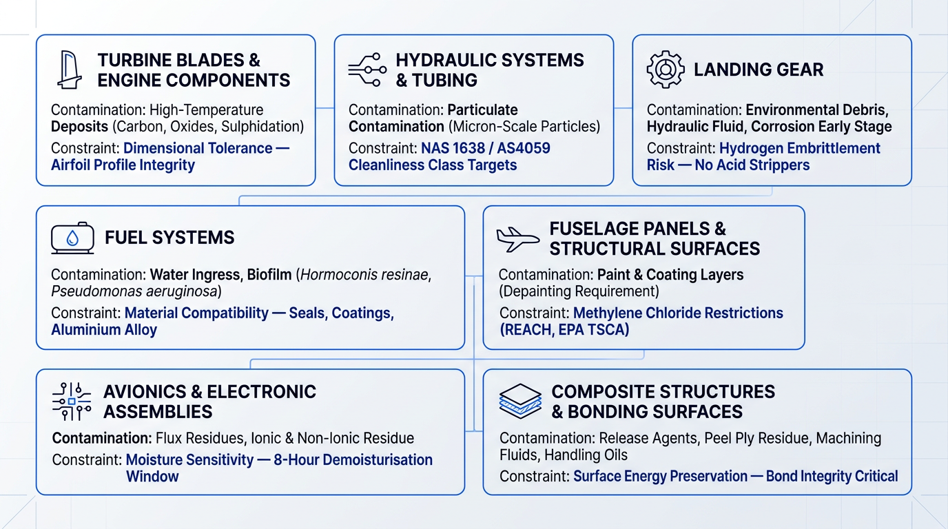
The seven component categories below cover the breadth of what aerospace cleaning professionals encounter — from engine internals to structural surfaces to electronic assemblies. Each presents a distinct set of constraints that shapes which approaches are viable and which are not.
Turbine blades and engine components
Turbine blades accumulate tenacious high-temperature deposits during service — carbon coking, metallic oxides, and sulphidation products that are chemically bonded to the blade surface rather than simply sitting on it.
What makes this one of the most demanding aerospace cleaning contexts is the combination of hard-to-remove contamination with a substrate that cannot tolerate aggressive treatment: blades operate to extremely tight dimensional tolerances, and even minor material removal from the airfoil profile alters both aerodynamic and thermal performance.
The geometry compounds the challenge further. Internal cooling passages — narrow channels that run through the blade body — cannot be reached by line-of-sight cleaning methods, so any approach must either penetrate those passages or be combined with a secondary method that does.
Hydraulic systems and tubing
In hydraulic systems, the contamination of concern is not visible to the naked eye. Particulate contamination — particles too small to see — is the dominant risk driver, because even microscopic solid particles cause progressive wear in servo-valves, damage seals, and can trigger system malfunction.
The NASA contamination reference data for aerospace-grade hydraulic systems classifies them as "super critical" — requiring particle counts at 5-micron and 15-micron size ranges that are orders of magnitude lower than general industrial hydraulic systems.
Cleanliness requirements for aircraft hydraulic systems are expressed as quantified cleanliness class targets under NAS 1638 and AS4059 — the two widely-used particulate contamination classification frameworks for hydraulic fluids — rather than as visual or gravimetric pass/fail criteria. SAE ARP5891A sets out the processes for achieving those targets during manufacture, covering tubing fabrication, flushing of the installed system, and final verification.
Achieving those targets requires methods capable of displacing and capturing particles from complex internal geometries — flushing and ultrasonic cleaning are common approaches, but the geometry of assembled tubing and valve bodies makes verification as important as the cleaning process itself.
Landing gear
Landing gear accumulates the full spectrum of environmental contamination: mud, runway debris, hydraulic fluid, de-icing compounds, and the early stages of corrosion — all on components that are structurally critical and made from high-strength steel.
Cleaning serves a dual purpose here that is closely linked: the surface must be clean enough to allow accurate corrosion inspection, and then clean enough again to allow effective corrosion treatment. You cannot inspect what you cannot see, and you cannot treat a surface that still carries contamination residue.
FAA AC 43-4B is explicit on the material constraint: acid-based chemical strippers must not be used on high-strength steel parts, because they introduce a risk of hydrogen embrittlement — a failure mode where atomic hydrogen diffuses into the steel lattice and reduces its fracture toughness. The cleaning method selection is therefore bounded not just by what removes the contamination, but by what the substrate can safely tolerate.
Fuel systems
Fuel system contamination involves a profile that is distinct from any other component category: water ingress, sediment accumulation, and — most consequentially — microbial biofilm growth at the fuel/water interface.
FAA AC 20-29C notes that the presence of free water in fuel can promote the growth of microorganisms including bacteria, yeast, and mould, leading to filter plugging, corrosion of metallic structures such as wing tanks, and degradation of protective coatings and electrical insulation.
The risk is amplified during extended periods of low utilisation. Lufthansa Technik's research, reported in Aviation Week, found that aircraft with long ground times — particularly in warm, humid conditions — are especially susceptible to biofilm formation, and that once established, biofilm is resistant to biocide treatment because the film itself protects the organisms from chemical attack. Christian Siry of Lufthansa Technik described how biofilm attacks tank walls through acidic micro-channels formed within the film, and noted that "the mixing of biocides with the fuel is not resolving the problem once the biofilm formation has been established."
The fungi Hormoconis resinae and the bacterium Pseudomonas aeruginosa have been specifically identified in peer-reviewed literature as contributors to pitting corrosion in fuel tank bottoms — a failure mode that is not always detected until inspection.
Material compatibility is a binding constraint throughout fuel system cleaning: any cleaning agent must be compatible with fuel system seals, protective coatings, and the aluminium alloy structures that make up the tank walls, as confirmed by FAA AC 20-29C and related guidance.
Fuselage panels and structural surfaces
The scale of cleaning shifts dramatically at the fuselage level. Depainting — the removal of paint and coatings from large external surfaces — is one of the most operationally significant cleaning operations in MRO, required for corrosion control, structural inspection, and surface preparation ahead of re-coating.
Chemical strippers based on methylene chloride (dichloromethane) were the industry standard for large-area depainting for decades. Regulatory pressure has now sharply curtailed their use: the EU's REACH Annex XVII Entry 59 restricted DCM-based paint strippers for professional and consumer use from 2010/2011 onwards, and in the United States, the EPA's 2024 TSCA final rule prohibits most industrial and commercial uses of methylene chloride, with a time-limited 10-year exemption granted specifically for civilian aviation paint and coating removal from safety-critical, corrosion-sensitive components — subject to strict workplace chemical protection programme requirements.
Alternative methods are gaining traction in response. Plastic media blasting has been used across US military depots for decades as a chemical-free depainting method for aluminium airframes. Laser-based coating removal is an emerging alternative: the US Navy's Fleet Readiness Center East has tested laser ablation for aircraft component depainting, and robotic laser systems are now being deployed commercially for full-aircraft stripping, with claims of significantly reduced turnaround time and near-elimination of chemical waste compared to solvent-based methods.
Avionics and electronic assemblies
In avionics, the contamination challenge is chemical rather than mechanical. Flux residues, handling contamination, and other ionic and non-ionic residues must be removed before conformal coating or encapsulation — because residual ionic contamination in the presence of moisture and electrical bias leads to electrochemical migration and dendritic growth, both of which degrade insulation resistance and can cause circuit failure.
NASA-STD-8739.1B makes the requirement explicit: prior to bonding, staking, conformal coating, or encapsulating, the assembly must be cleaned to remove ionic and non-ionic residue and demoisturised, and the cleaning process must not deposit residue on electrical contact surfaces such as switches, potentiometers, or connectors.
Moisture sensitivity is the key method constraint. Aqueous cleaning is effective at removing ionic residues, but requires careful drying protocols before conformal coating can be applied — NASA-STD-8739.1B requires cleaning, cleanliness testing, and demoisturisation to be completed within 8 hours before coating. Some assemblies cannot tolerate any liquid exposure at all, which eliminates aqueous approaches entirely and shifts the requirement toward solvent-based or vapour-phase methods.
Composite structures and bonding surfaces
Pre-bond surface preparation of composite structures is a precision cleaning discipline, not a routine maintenance task. NASA NTRS research (20170006189) has demonstrated that a range of common contaminants — including release agents, peel ply residue, machining fluids, latex, silicone, and even handling oils from fingerprints — measurably reduce the fracture toughness of adhesive bonds in carbon fibre reinforced epoxy structures.
The cleaning method must remove contamination without altering surface energy, which governs how well an adhesive wets and spreads across the bonding surface. This is where the cleaning process can create a new problem while solving the original one: a solvent wipe that leaves trace residue, or an abrasive process that changes surface chemistry, can leave a surface that looks clean but bonds poorly.
FAA AC 43-214A references SAE ARP4916 (Masking and Cleaning of Epoxy and Polyester Matrix Thermosetting Composite Materials) as the governing procedure, requiring that composite surfaces be cleaned with chemicals approved by the structural repair manual or other FAA-accepted data, and that excess cleaning fluids be fully removed before further processing.
For every aerospace component, the combination of geometry, base material, contamination type, and downstream use produces a distinct cleaning requirement — which is why the same method that works for hydraulic tubing is unsuitable for avionics boards, and the approach that cleans a turbine blade safely would be inadequate for a composite bond surface. Method selection must start with the component.
Each of these component-specific requirements exists within a broader framework: the industry has formalised many of them into cleanliness standards, specifications, and regulatory requirements that define what "clean enough" actually means in measurable terms. That compliance landscape is where the next section picks up.
Aerospace cleanliness standards: the regulatory landscape
Every cleanliness target in aerospace has a formal answer behind it. The question "how clean is clean enough?" is not left to engineering judgement on the shop floor — it is resolved by a structured body of standards that quantify acceptable contamination levels, specify approved cleaning materials, and define the regulatory conditions under which alternative methods may be introduced.
That body of standards is not flat. Programme-level contamination control plans sit at the top, defining the specific cleanliness requirements for a given system or component by referencing the applicable classification standards. Below them sit the cleanliness classification standards themselves — IEST-STD-CC1246, NAS 1638, ISO 4406 — and below those, the method-level specifications (SAE AMS and ARP) that govern which materials and processes are approved for specific cleaning tasks.
Understanding this hierarchy is the prerequisite for every downstream decision: which verification method applies, which cleaning chemistry is permissible, and which regulatory pathway must be followed when introducing a new technology.
Spacecraft and precision hardware: NASA-STD-6016 and IEST-STD-CC1246
NASA-STD-6016 governs materials and processes for spacecraft flight hardware across all NASA manned, unmanned, robotic, launch vehicle, lander, and in-space systems — including vendor-designed, off-the-shelf, and vendor-furnished items. Its scope extends to ground support equipment, test equipment, and hardware packaging when those items interface with flight hardware.
The standard's defining principle is that cleaning and surface preparation are controlled processes, not incidental workshop tasks. Process specifications for mission-critical flight hardware must define process steps at a level of detail that ensures a repeatable, controlled process producing a consistent and reliable product — and process qualification must demonstrate that repeatability. Each NASA programme operating under this standard is required to maintain a Contamination Control Plan (CCP) as a formal programme document.
IEST-STD-CC1246 is the aerospace industry's primary standard for defining product cleanliness levels. It governs two distinct contamination categories: particulate cleanliness levels, expressed as particle size and count limits per 0.1 m², and molecular cleanliness levels expressed as non-volatile residue (NVR) limits in mg/0.1 m².
A cleanliness level designation under IEST-STD-CC1246 encodes both dimensions. A numerical level — such as Level 200 — refers to particulate contamination only, where the number represents the maximum particle size (in µm) permitted at an average distribution of one particle per square foot of surface area. An alphabetical designation — such as Level A — refers to NVR only, where Level A permits a maximum of 1 mg/0.1 m². A combined designation such as Level 200A specifies both particulate and NVR limits simultaneously, and is a more stringent requirement than Level 200B for both categories.
Hydraulic systems: NAS 1638, SAE AS4059, and ISO 4406
NAS 1638 was developed specifically for aerospace fluid power components and remains widely used across industrial and aerospace hydraulic applications. It classifies fluid cleanliness using differential particle counts per 100 mL of fluid across five size ranges: 5–15 µm, 15–25 µm, 25–50 µm, 50–100 µm, and greater than 100 µm. The NAS class is reported as a single figure representing the worst-case maximum across all size ranges — NAS Class 00 permits 125 particles in the 5–15 µm range per 100 mL, while NAS Class 12 permits 1,024,000.
SAE AS4059 is the successor to NAS 1638 and is now the preferred reference for new aerospace hydraulic system designs. It uses the same contamination class structure but adds versatility: a single maximum class can be specified across all size ranges, or a separate class can be designated for each individual size range. The class-to-system-sensitivity mapping is direct — servo valves and high-performance hydraulic actuators typically require AS4059 Class 7 or cleaner, while general hydraulic systems operate at higher class numbers.
ISO 4406 provides a parallel reporting system for hydraulic fluid particulate contamination, using a three-number code. The three numbers represent ISO range codes for cumulative particle counts at thresholds of ≥4 µm(c), ≥6 µm(c), and ≥14 µm(c) per millilitre of fluid. For example, an ISO code of 21/19/16 indicates between 10,000–20,000 particles ≥4 µm, 2,500–5,000 particles ≥6 µm, and 320–640 particles ≥14 µm per mL. Servo control valves in aerospace applications typically require ISO 16/14/11 or cleaner — a super-critical classification in the ISO sensitivity hierarchy.
NAS 1638 and ISO 4406 are used in parallel across the industry, and practitioners routinely need to read both. The Parker contamination standards guide provides a cross-reference table mapping NAS classes to ISO codes and AS4059 designations — a practical tool when specifications from different programmes or eras use different systems.
| Standard | Governing Body | What It Measures | How Cleanliness Is Expressed | Applicable System / Hardware |
|---|---|---|---|---|
| NASA-STD-6016 | NASA | Materials and processes for flight hardware; cleaning as a controlled process | Programme CCP defines specific cleanliness requirements referencing applicable standards | All NASA spacecraft and flight hardware, including vendor items |
| IEST-STD-CC1246 | IEST | Particulate (size/count per 0.1 m²) and molecular NVR (mg/0.1 m²) | Numerical level (e.g. Level 200) for particulate; alphabetical (e.g. Level A = 1 mg/0.1 m²) for NVR; combined (e.g. 200A) | Precision spacecraft hardware, optical surfaces, propulsion components |
| NAS 1638 | AIA / NAS | Differential particle counts per 100 mL across 5 size ranges (5–15 µm to >100 µm) | Single NAS class (00 to 12); worst-case across all size ranges | Aerospace and industrial hydraulic fluid power systems |
| SAE AS4059 | SAE International | Differential particle counts per 100 mL across 6 size ranges (MTD) or 5 (ACFTD) | Single class or per-size-range class designation (000 to 12); successor to NAS 1638 | Aircraft hydraulic systems; preferred standard for new designs |
| ISO 4406 | ISO | Cumulative particle counts at ≥4 µm(c), ≥6 µm(c), ≥14 µm(c) per mL | Three-number ISO range code (e.g. 16/14/11); each number maps to a particle count range | Hydraulic fluid systems across aerospace and industrial applications |
| SAE ARP5891A | SAE International | Processes for achieving cleanliness during fabrication, assembly, and functional test | References NAS 1638 / AS4059 class targets; governs flushing and final verification | Aircraft hydraulic systems during manufacture |
| EPA NESHAP (40 CFR Part 63, Subpart GG) | US EPA | HAP and VOC emissions from cleaning, depainting, primer/topcoat, and maskant operations | Composition requirements, vapor pressure limits (≤45 mm Hg at 20°C), or volume reduction | Aerospace manufacturing and rework facilities that are major HAP sources |
Overview of the major aerospace cleanliness standards — governing body, what they measure, how cleanliness is expressed, and applicable system or hardware type — to give readers a navigable landscape before the prose develops each standard in detail.
What the table reveals is that no single standard governs all aerospace cleaning applications. Spacecraft hardware, hydraulic systems, and regulated manufacturing facilities each sit under a different primary framework — yet all of them are answering the same engineering question: what level of contamination is acceptable for this system to perform reliably, and how is that level quantified and verified?
The hydraulic standards (NAS 1638, AS4059, ISO 4406) are particularly instructive because they make the sensitivity gradient explicit: the cleanliness class required for a servo valve is several orders of magnitude more stringent than for a ram pump or cylinder. That gradient is not arbitrary — it reflects the clearances inside each component and the consequence of particulate ingestion at those clearances.
SAE AMS and ARP specifications: method-level requirements
Where classification standards define the cleanliness target, SAE AMS and ARP specifications define the approved means of reaching it. These are the method-level layer of the compliance hierarchy — they tell practitioners which materials and processes are qualified for specific cleaning tasks.
- AMS3819: Specifies absorbent fabric materials — dry or pre-saturated — for solvent cleaning of primary and secondary structural surfaces.
- AMS3167: Covers liquid solvent cleaners used for wipe cleaning prior to application of primer, topcoat, or sealing compounds.
- AMS03_2: Specifies processes for cleaning metal surfaces to remove extraneous deposits at any stage of manufacture, storage, or service.
- ARP5891A: Provides processes for achieving cleanliness standards during fabrication, assembly, and functional test of aircraft hydraulic systems, including tubing and flushing.
- ARP1755: Covers the stock loss test method for determining material removal caused by chemical cleaning agents on aircraft turbine engine materials.
ARP1755 is worth singling out because it addresses a constraint that goes beyond cleanliness: it quantifies the effect of cleaning chemistry on the base material itself, ensuring that the act of cleaning does not compromise the structural or dimensional integrity of turbine engine components.
FAA regulatory framework and the AMOC process
The FAA does not prescribe specific cleaning methods — it governs what is permissible through advisory circulars and airworthiness directives. AC 43-206 covers the cleaning and preservation of avionics equipment, specifying approved materials and techniques for equipment bays, external cases, and electronic components. AC 43-4B addresses corrosion control for aircraft, establishing that cleaning is a foundational and recurring element of any corrosion prevention and control programme — not a one-time preparation step.
The governing regulatory principle is that any alternative cleaning agent or process must not degrade airworthiness. When a new cleaning agent or method is introduced as an alternative to one specified in a manufacturer's maintenance instructions, equivalency must be demonstrated and the Alternative Method of Compliance (AMOC) process applies under 14 CFR 39.19.
An AMOC proposal is submitted to the appropriate FAA office — typically through the Principal Inspector — and must include a complete technical description of the alternative process and substantiating data showing that it resolves the unsafe condition with an acceptable level of safety. The responsible office manager holds approval authority, though in some cases this authority is delegated to designated engineering representatives (DERs) or organisation designation authorisation (ODA) holders. This is the formal regulatory pathway through which newer cleaning technologies enter FAA-regulated maintenance operations.
Environmental regulation: EPA NESHAP for aerospace facilities
Environmental regulation is not a background constraint on aerospace cleaning chemistry — it is a direct operational limit. The EPA National Emission Standards for Hazardous Air Pollutants (NESHAP) for aerospace manufacturing and rework facilities, codified at 40 CFR Part 63, Subpart GG, applies to major HAP sources and sets binding limits on emissions from cleaning operations, depainting, primer and topcoat application, and chemical milling maskant operations.
The HAPs specifically targeted by the NESHAP that are historically prevalent in aerospace cleaning include methylene chloride, toluene, xylene, methyl ethyl ketone (MEK), glycol ethers, chromium, cadmium, and ethylene glycol. The rule requires that hand-wipe and flush cleaning solvents either meet an approved composition list, have a composite vapor pressure of 45 mm Hg or less at 20°C, or achieve a 60 percent volume reduction from an approved baseline.
For facilities that are major HAP sources, these requirements directly constrain which solvents can be used in cleaning operations — and they interact with FAA maintenance requirements when a specified cleaning agent falls outside the NESHAP's permissible composition. That intersection is precisely what drove the development of alternative cleaning pathways and the AMOC process described above. The environmental and chemistry selection implications are developed further in the next section.
A programme-level Contamination Control Plan defines the cleanliness requirement for a specific component and application by referencing the applicable classification standard. Method selection — which cleaning technology and chemistry to use — must be validated against that requirement, not chosen on technical capability alone. Selecting a method before identifying the applicable cleanliness class inverts the process.
Knowing what the standards require is only half the compliance picture. The next question is how conformance is demonstrated — through particle counting, gravimetric NVR analysis, and the documentation that makes cleanliness verifiable and traceable for airworthiness purposes. That is the subject of the following section.
Cleanliness Verification and Documentation
Cleaning a component and proving it is clean are two distinct engineering activities — and in aerospace, only the second one counts for compliance purposes. A cleaning operation that cannot be verified and documented is, from an airworthiness perspective, an incomplete operation.
There are five principal verification methods used across aerospace cleaning programmes, each targeting a different aspect of surface cleanliness. Selecting the right method — or combination of methods — depends on the contamination type of concern, the applicable cleanliness class, and the downstream use of the component.
Particle Counting via Liquid Flush Testing
Particle counting is the primary quantitative method for verifying particulate cleanliness. The component is flushed with a verification fluid — a precision-cleaned solvent or deionised water that itself meets the cleanliness requirements for the level being tested — and the flush effluent is passed through a membrane filter, typically 0.45 micron pore size.
Particles captured on the filter are counted and sized under microscopy per ASTM F312 or SAE ARP 598, and the result is normalised to the component's wetted surface area, expressed as particles per 0.1 m². Per NASA LaRC LPR 1740-5G, the standard test sample volume is 100 mL of flush fluid per 0.1 m² of critical surface area.
Results are mapped against the applicable cleanliness class limits. Under IEST-STD-CC1246, the cleanliness level number (e.g. Level 100, Level 400, Level 1000) represents the largest particle size permitted within the statistical distribution for that surface. Under NAS 1638 and AS4059, limits are expressed as differential particle counts per 100 mL across defined size ranges — for example, NAS Class 6 permits a maximum of 16,000 particles in the 5–15 µm range, 2,850 in the 15–25 µm range, 506 in the 25–50 µm range, 90 in the 50–100 µm range, and 16 above 100 µm.
The critical limitation of particle counting is its scope: it captures particulate contamination only. It provides no information on molecular contamination — oils, greases, and organic films that may be present at levels that would compromise performance but are invisible to the particle count result.
Gravimetric NVR Analysis
Gravimetric analysis addresses the molecular contamination gap that particle counting cannot fill. In the standard method, the component or a representative coupon is flushed with an approved solvent; the solvent is then evaporated and the residue weighed. The result is expressed in mg per 0.1 m² of wetted surface area and compared against the applicable NVR level.
IEST-STD-CC1246 defines a graduated series of NVR levels using letter designations. From NASA programme data, Level A corresponds to a maximum of 1 mg per 0.1 m², Level B to 2 mg, Level C to 3 mg, continuing through to Level J at 55 mg per 0.1 m². Sub-level designations extend down to Level A/100 (0.01 mg per 0.1 m²) for the most contamination-sensitive applications.
NVR limits are the binding constraint wherever molecular cleanliness is critical — oxygen systems, cryogenic fluid lines, and spacecraft optics. For many hydraulic and pneumatic system components, particulate limits under NAS 1638 or AS4059 are the primary concern, with NVR requirements applied selectively based on system sensitivity.
A practical complexity of gravimetric NVR testing is that the verification fluid itself must be certified clean before use. Per NASA MSFC-SPEC-164E, the NVR background of the flush solvent must not exceed 3 mg per 100 mL for sampling to Level B, or 0.4 mg per 100 mL for sampling to Level A — ensuring the measurement is not confounded by residue introduced by the test fluid.
Contact Angle Measurement
Contact angle measurement is a surface energy indicator particularly relevant to bonding applications. A small water droplet is deposited on the surface; the angle between the droplet edge and the substrate is measured — a low contact angle approaching 0° indicates high surface energy and good wettability, characteristic of a clean surface ready for adhesive bonding.
A high contact angle indicates hydrocarbon film contamination that would compromise bond performance. Instruments such as the Surface Analyst use a ballistic deposition method to place a precisely controlled 2 µL water droplet, generating a repeatable measurement in seconds that can be configured as a go/no-go gate for pre-bond surface preparation.
The key limitation is that contact angle is a point measurement. As noted by Boeing Research & Technology technical fellow Kay Blohowiak in CompositesWorld, there are no techniques to measure 100% of the bondline — a sampling methodology must be defined to demonstrate reliability across the full bonded joint, with more measurements recommended near bondline edges where contamination drag-in is more common.
Contact angle measurement is not a substitute for NVR or particle counting. It is a complementary surface energy indicator that gives rapid, in-process feedback on surface preparation quality — particularly useful as a production quality gate before bonding operations proceed.
Visual Inspection Levels
Visual inspection operates across three defined tiers. Generally Clean (GC) confirms freedom from gross manufacturing residue, dirt, oil, and grease — appropriate for hardware not sensitive to contamination. Visibly Clean (VC) requires the absence of all particulate and non-particulate matter visible to the unaided eye under specified illumination, typically 50 foot-candles at an inspection distance of 2–10 feet depending on sensitivity tier.
UV inspection adds ultraviolet light examination to detect fluorescent hydrocarbon films invisible under white light — specified for hardware that cannot tolerate hydrocarbon build-up between operations, and sometimes designated as VC+UV to reflect the combined requirement.
The critical principle governing all visual inspection is that it is a screening tool and a prerequisite, not a precision cleanliness verification method. It cannot detect sub-visible particles or thin molecular films below the resolution limit of the human eye.
NASA contamination control research indicates that standard VC inspection can verify surface particle cleanliness to approximately Level 1000 at around 2 metres viewing distance, with higher-sensitivity VC conditions at closer distances resolving somewhat finer levels — though the exact threshold varies with surface colour, illumination angle, and particle type. Visual inspection confirms gross cleanliness before more rigorous quantitative verification proceeds; it does not replace it.
FTIR Spectroscopy
FTIR spectroscopy is an emerging specialist verification method for identifying specific organic contaminants on bonding surfaces. An attenuated total reflectance (ATR) or reflectance measurement passes infrared radiation through or across the surface, producing a spectral fingerprint that can identify the molecular structure of surface residues — including silicone-containing mould release agents, hydrocarbon films, and other organic contaminants that gravimetric NVR analysis can quantify but cannot chemically identify.
This capability is particularly relevant to composite pre-bond surface preparation, where siloxane contamination from peel ply release agents is a primary cause of bond failure. Instruments such as the Agilent ExoScan Surface FTIR can measure contaminant levels in µg/cm² and deliver a go/no-go result against calibrated thresholds, with measurements typically taken every 6–12 inches along a bondline.
FTIR is not a routine production verification method — it requires calibrated analytical equipment and trained interpretation. Its value is qualitative identification: it tells you not just how much residue is present, but what it is, which matters when a bond failure investigation needs to trace the contamination source or when a pre-bond process is being validated for the first time.
Documentation and Traceability
The documentation layer that binds verification to compliance is not administrative overhead — it is a substantive airworthiness and quality requirement. NASA-STD-6030 states explicitly that failure to properly control cleaning procedures can lead to contamination-related failures, and that cleanliness levels and methods of verification must be governed by the contamination control plan for the hardware.
The regulatory structure of EASA Part-145, NASA standards, and AS9100 makes an undocumented cleaning operation functionally equivalent to one not performed: without a traceable record, there is no basis for airworthiness sign-off, no audit trail, and no means of reconstructing what was done if a component subsequently fails. A complete cleanliness record for a precision-cleaned component typically covers all of the following elements.
- Cleaning process record: Method, chemistry, parameters, equipment used, and cleaning environment (cleanroom class or equivalent).
- Verification method and results: Particle count data, NVR gravimetric results, contact angle readings, or other applicable verification outputs.
- Cleanliness level achieved vs. required: Explicit comparison of the measured result against the specified cleanliness class limit.
- Verification fluid traceability: Certification that the flush solvent or test fluid met the NVR and particulate requirements for the level being verified.
- Operator and inspector identity: Named individuals responsible for performing the cleaning and conducting the verification inspection.
- Component serialisation and date: Part number, serial number, and date of cleaning and verification, supporting return-to-service and audit traceability.
This documentation chain supports three distinct functions: airworthiness return-to-service authorisation, quality audit trails under AS9100 and EASA Part-145, and — critically — the ability to reconstruct exactly what was done in the event of a component failure.
The traceability requirement extends to the verification consumables themselves. The flush solvent used for NVR sampling must be certified to meet the NVR background limit for the level being tested — a requirement that creates its own procurement and documentation burden, since each batch of verification fluid must be qualified before use.
Cleaning Method Choice and Verification Burden
The choice of cleaning method does not end at the cleaning step — it directly shapes the verification programme that follows. This is an underappreciated operational reality that affects process design, cycle time, and documentation scope.
With aqueous detergent or solvent-based cleaning, the cleaning agent itself becomes a potential contaminant. Residual chemistry must be verified as removed — typically via an additional rinse stage and NVR check, or through validated rinsing protocols demonstrated to reduce cleaning agent residue to below detectable limits. Dry methods (laser, dry ice blasting, CO2 snow) introduce no chemistry into the process, so there is no secondary contamination source to verify. The verification scope is correspondingly simpler.
For chemistry-based processes, the rinse validation burden is substantial. NASA JSC PRC-5001 requires that flammable solvents used for cleaning be verified as removed to below 18 ppm (measured as methane) or 10 ppm on a solvent-specific calibrated instrument, following a minimum 24-hour inert gas purge and lockup — a verification step with its own documented procedure, its own pass/fail threshold, and its own place in the traceability record, added purely because a solvent was used.
This is not an argument against chemistry-based cleaning — it is a practical observation about the total verification workload those methods carry. For verification-intensive applications where documentation burden and cycle time are operational constraints, the absence of residual chemistry in dry cleaning processes is a genuine process design advantage worth factoring into method selection.
The verification burden of cleaning chemistry is one dimension of a broader set of operational and regulatory considerations those methods carry. The next section examines the environmental and worker safety implications of cleaning chemistry selection — the regulatory frameworks governing VOC and HAP emissions, worker exposure limits, and the industry's response to those pressures.
Environmental and Worker Safety Trade-offs in Chemistry Selection
Most method selection discussions in aerospace cleaning focus on technical performance — cleaning effectiveness, material compatibility, and cleanliness verification. The environmental and worker safety dimension tends to get treated as a compliance afterthought: something the EHS team handles separately. That framing is increasingly untenable. Cleaning chemistry selection now carries regulatory obligations, engineering control burdens, and hazardous waste liabilities that are structural constraints on method selection — not optional considerations to be managed around the edges.
The Regulatory Framework: NESHAP, HAPs, and VOC Limits
The primary US federal framework governing cleaning chemistry in aerospace is the EPA's National Emission Standards for Hazardous Air Pollutants (NESHAP) for aerospace manufacturing and rework facilities, codified under 40 CFR Part 63 Subpart GG. The rule covers all hand-wipe cleaning, flush cleaning, and spray gun cleaning operations at facilities that are major sources of hazardous air pollutants (HAPs) — defined as facilities emitting more than 10 tons per year of any single HAP, or more than 25 tons per year of any combination.
The HAPs historically prevalent in aerospace cleaning operations include methylene chloride, toluene, xylene, methyl ethyl ketone (MEK), and 1,1,1-trichloroethane, alongside chromium, cadmium, ethylene glycol, and glycol ethers. The NESHAP rule was designed to achieve a 60% reduction in air toxics emissions from the aerospace manufacturing and rework sector — a reduction of approximately 123,000 tons annually — and it does so by constraining which cleaning chemistries facilities may use across each regulated operation.
For hand-wipe and flush cleaning operations specifically, the EPA's Control Technique Guideline (CTG) for aerospace manufacturing sets a composite vapour pressure limit of ≤45 mm Hg at 20°C for any solvent used. Facilities must use cleaning solvents that are either aqueous (with water as the primary ingredient, comprising more than 80% of the solution as applied) or have a VOC composite vapour pressure at or below that threshold. In practice, this eliminates a wide range of traditional cleaning solvents — MEK, for instance, has a vapour pressure of approximately 78–90 mm Hg at 20–25°C, which places it well above the permissible limit for uncontrolled hand-wipe use.
The approved solvent composition categories under the CTG — aqueous, hydrocarbon-based reduced vapour pressure, and similar formulations — reflect a deliberate narrowing of the chemistry options available to aerospace facilities. This is not merely a documentation exercise: facilities using non-compliant solvents face enforcement exposure, and the monitoring and recordkeeping requirements attached to solvent use add an ongoing administrative burden to every cleaning operation.
Worker Exposure and the Engineering Controls Burden
Beyond the emissions framework, OSHA Permissible Exposure Limits (PELs) create a parallel set of constraints on cleaning chemistry selection from the worker protection side. The PELs for the five HAPs most prevalent in aerospace cleaning vary considerably: methylene chloride carries a particularly stringent 8-hour TWA PEL of just 25 ppm (reduced from 500 ppm in a 1997 OSHA rulemaking, reflecting its classification as a probable carcinogen), while toluene and MEK are set at 200 ppm TWA, xylene at 100 ppm TWA, and 1,1,1-trichloroethane at 350 ppm TWA.
Modern vapour degreasing fluids have evolved specifically in response to this regulatory pressure, with formulations designed to carry PELs of 200–1,000 ppm — substantially higher than the older halogenated solvents they replace, meaning meaningfully lower toxicity risk for workers at equivalent airborne concentrations. Many modern fluids are also not classified as HAPs and carry low or zero ozone-depleting potential, which simplifies the compliance picture considerably compared to legacy chemistries.
However, even compliant modern solvents require a set of engineering controls that represent a continuous operational overhead, not a one-time capital investment. The EPA NESHAP and OSHA standards together mandate specific work practices for any facility using regulated cleaning solvents:
- Local exhaust ventilation (LEV): Required to capture solvent vapours at the source and prevent accumulation in the work area; must be designed and installed by a qualified specialist.
- Closed containers for cleaning agents: Fresh and spent solvents must be stored in sealed containers to contain vapours and prevent evaporative emissions between uses.
- Solvent-laden rag containment: Rags or wipes used in cleaning must be placed in sealed bags or closed containers immediately after use to contain residual vapour.
- Spill and transfer controls: Handling and transfer procedures must minimise spills during filling and decanting, with prompt clean-up protocols for any releases.
These controls are not installed and forgotten. They require periodic monitoring to verify that worker exposures remain below applicable PELs, documented recordkeeping for each cleaning solvent used (including product name, vapour pressure, and HAP constituent documentation), and — for methylene chloride specifically — air monitoring every three to six months and medical surveillance for exposed workers. For a busy MRO facility running multiple cleaning operations in parallel, this represents a substantial and recurring management commitment.
Aqueous vs. Solvent: Different Trade-offs, Not a Clear Winner
A common assumption is that switching from solvent-based to aqueous cleaning resolves the environmental and safety problem. The reality is more nuanced: aqueous systems eliminate organic solvent vapour exposure for workers, but they introduce a different set of environmental obligations. Wastewater generated by aqueous cleaning undergoes a multi-stage treatment process — filtration, distillation, deionisation, and osmosis preparation — before it can be safely disposed of, and that treatment process carries both cost and regulatory compliance requirements of its own.
Aqueous systems also consume significantly more energy than modern solvent-based alternatives, primarily through water heating and the energy-intensive drying stages required after cleaning. Modern closed-loop vapour degreasers use no water, require no wastewater treatment, and consume less electricity than equivalent aqueous systems — the solvent is continuously redistilled and recycled within the machine, reducing both waste generation and hazardous waste disposal costs. The trade-off is that the solvent chemistry itself still requires HAP and VOC monitoring, hazardous waste disposal for spent fluid, and the engineering controls burden described above.
Neither approach is a clean winner on all environmental and safety axes. Aqueous cleaning shifts the burden from air quality and worker vapour exposure toward wastewater management and energy consumption. Solvent-based cleaning, even with modern lower-toxicity formulations, retains the chemistry compliance overhead. For complex geometries, aqueous systems also introduce moisture-related risks that require careful process management — a practical consideration that compounds the energy cost of thorough drying. The right choice between them depends on the specific facility's regulatory position, wastewater treatment infrastructure, and energy costs, not on a universal environmental preference.
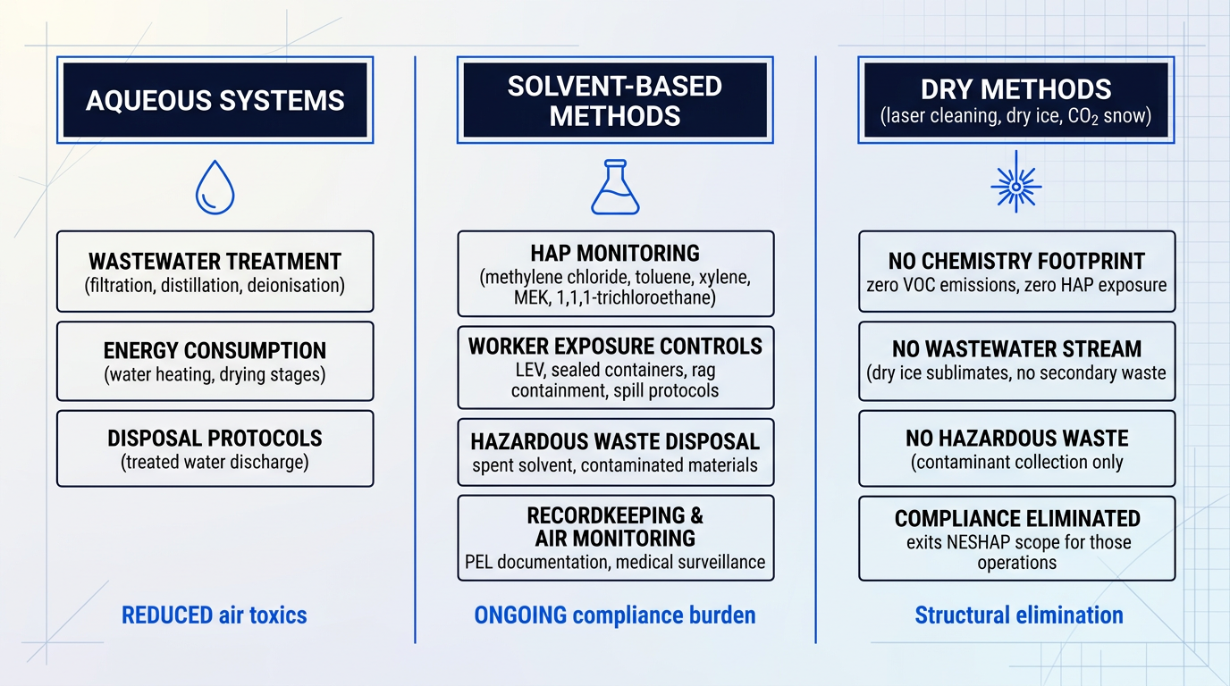
Laser cleaning, dry ice blasting, and CO2 snow cleaning occupy a categorically different position on the environmental and safety spectrum. These dry methods introduce no cleaning chemistry into the process: there are no VOC emissions, no HAP exposure, no wastewater stream, and no chemical waste requiring hazardous disposal. Dry ice sublimates on contact, leaving only the removed contaminant to be collected — there is no secondary waste medium to manage. The compliance overhead that defines chemistry-based cleaning is not reduced by these methods; it is eliminated entirely.
This is not a niche preference or a marginal environmental benefit. It is a structural response to the regulatory direction of travel — and increasingly, to sustainability mandates embedded in aerospace prime contractor supply chain requirements, which are pushing tier-1 and tier-2 suppliers to document and reduce their chemical footprint. Facilities that have shifted to dry cleaning methods report that the absence of solvent chemistry removes an entire category of compliance obligation from their operations.
Under EPA RCRA regulations, facilities that reduce or eliminate HAP-containing solvents can move to less stringent hazardous waste generator categories — from Large Quantity Generator to Small Quantity Generator or Very Small Quantity Generator status — unlocking reduced regulatory requirements, lower monitoring and reporting burdens, and materially lower hazardous waste disposal costs. This is a quantifiable business case for chemistry reduction, not just an environmental preference.
The operational and financial consequences of chemistry reduction are concrete. Facilities that permanently eliminate regulated HAP solvents can, under EPA policy, exit the scope of the NESHAP rule for those operations entirely. Reduced hazardous waste volumes lower disposal costs directly, and the monitoring, recordkeeping, and reporting requirements that attach to solvent use shrink in proportion to the chemistry footprint. For procurement and operations teams building the business case for method selection, these are quantifiable line items — not environmental virtue signalling.
With the regulatory and safety picture established, the next dimension of method selection is how these choices play out on the production floor — in throughput, cycle time, labour intensity, and automation potential.
Throughput, Automation, and MRO Turnaround
Technical performance and regulatory compliance set the floor for method selection — but they do not determine whether a cleaning process fits the production schedule, the MRO bay, or the labour budget. Cycle time, automation potential, and the question of whether a component must be removed before it can be cleaned are operational consequences that can shift total cost and turnaround time as significantly as cleaning performance itself.
Cycle Time and Process Stages
Cleaning methods differ not just in how fast they clean, but in how many discrete stages they require — and each stage is a scheduling dependency.
Aqueous cleaning involves a multi-stage sequence — wash, rinse, and dry — with drying representing a significant time contribution for components with complex internal geometries where trapped moisture is difficult to remove.
Vapour degreasing integrates cleaning, rinsing, and drying within a single closed-loop chamber, with typical cycle times in the 6–20 minute range; parts emerge clean, rinsed, dried, and ready for the next production stage without additional handling.
Ultrasonic cleaning reduces the manual manipulation time required to achieve consistent cleanliness: one aerospace manufacturer reported a 40% reduction in manual manipulation time after adopting ultrasonic systems, with a direct translation to cost savings across both manufacturing and service operations.
In-Place Cleaning and MRO Turnaround
In MRO contexts, the dominant variable in total turnaround time is often not the cleaning operation itself — it is the removal, disassembly, transport, reassembly, and reinstallation that surround it.
Dry methods — including dry ice blasting, CO2 snow, and laser cleaning — can clean components in-place at or near operating temperature, without cooldown or disassembly, removing that overhead from the schedule entirely.
Rolls-Royce's adoption of automated dry ice blasting for compressor rotor blade cleaning illustrates the scale of the opportunity: switching to in-place dry ice cleaning delivered a 90% cost saving on compressor blade cleaning and an 84% improvement in module turn time, while eliminating chemical agents from the process.
Aqueous immersion cleaning, by contrast, typically requires component removal and full disassembly — a meaningful scheduling overhead in time-critical MRO operations.
Automation and Labour Intensity
Automation potential varies substantially across cleaning methods and has direct implications for both throughput consistency and labour cost.
- Vapour degreasing: Integrates naturally into production lines and supports full batch automation, making it a strong fit for high-volume, high-throughput manufacturing environments.
- Dry ice blasting: Can be automated for repetitive tooling and mould cleaning applications, with cleaning frequency increasing when cooldown and disassembly are removed from the cycle.
- Laser cleaning: When the cleaning head is mounted on a robotic arm, delivers consistent cycle-to-cycle results on complex 3D components without operator skill as a variable.
The production-scale impact of automation is well documented in aerospace manufacturing: the F-35 forward fuselage programme achieved a 26% reduction in hours per unit — from 132 hours to 98 hours — through an integrated machine tool transfer line that unified machining, transfer, and washing operations, cutting monorail moves from 18 to 2 and reducing transportation time as the primary driver of the saving.
Manual cleaning methods — hand scraping, brush cleaning, hand-wipe solventing — introduce operator variability that is both an efficiency problem and a quality risk: the cleanliness outcome depends on the individual's technique, fatigue level, and attention on any given shift.
Automated cleaning processes hold the same parameters on every cycle, which directly supports the quality documentation requirements discussed earlier in this guide: logged cycle data provides the traceability record that manual cleaning cannot generate with the same reliability.
Automated cleaning systems carry higher capital cost than manual methods, but zero consumables, reduced labour, and eliminated rework from inconsistent outcomes shift the total cost of ownership calculation substantially — often making automation the lower-cost option over a multi-year operational horizon.
Laser Cleaning in the Operational Picture
Laser cleaning carries a specific operational profile worth understanding on its own terms: no consumables, no chemistry procurement cycle, no waste disposal scheduling, and no drying stage — the surface is ready immediately after cleaning.
For high-volume repetitive applications such as turbine blades and engine components, automated laser cleaning systems can hold a consistent cleanliness standard on every cycle without operator involvement in the cleaning decision.
Woodrow Scientific's AutoLASE automated laser cleaning system takes this a step further: its 3D machine-vision software scans the loaded part, builds a 3D map, and generates the cleaning path automatically — no manual programming, no path-setting, and no knowledge of part geometry required from the operator, so anyone can load a part and run it.
AutoLASE can also be configured with WSL's Reduced Hazard Zone technology, enabling enclosure-free automated cleaning — a capability exclusive to WSL that removes the facility-layout constraints conventional automated laser systems impose.
For MRO and open-facility contexts where portability matters, WSL's ELASER-RHZ portable laser cleaner addresses a distinct scheduling constraint: conventional laser cleaning requires work areas to be sealed off and evacuated before operation, adding overhead in busy facilities. The ELASER-RHZ's patented reduced hazard zone technology collapses the laser hazard zone to a fraction of conventional size, enabling cleaning in open workshops and mixed-use facilities without shutting down the surrounding area.
Throughput and automation determine how efficiently a cleaning method fits the production schedule — but equally important is what condition the surface is in once cleaning is complete, and whether that condition serves the process that follows.
Cleaning and Downstream Process Compatibility
Most cleaning evaluations stop at the same question: did the contamination come off? That question is necessary but not sufficient. The more consequential question — the one that determines whether a bonded joint holds, a coating adheres, or an NDT inspection returns a reliable result — is what the cleaning method left behind.
The substrate integrity principle frames this differently: a cleaning method must not create a new problem while solving the contamination problem. Abrasion can close surface-breaking flaws. Solvent wipe can deposit a residue film. Chemical treatment can alter surface chemistry. Each of these outcomes may be invisible to the eye and yet fatal to the downstream process that follows.
Surface Preparation for Adhesive Bonding
Contamination is the primary cause of adhesive bond failure in aerospace composite and metal structures. The cleaning method must remove hydrocarbon contamination, machining fluids, and release agent residues — but silicone-containing mould release residues present a particular challenge: silicone dramatically reduces surface energy and is notoriously difficult to detect visually, meaning a surface can appear clean while remaining chemically hostile to adhesion.
NASA Langley Research Center research has demonstrated that laser surface treatment removes silicone contamination and simultaneously creates surface roughness and chemical activation conducive to bonding. For titanium alloy bonding preparation specifically, NASA research showed that laser ablation can replace chemical deoxidation steps — including nitric and hydrofluoric acid treatment — with no loss in adhesion performance and full compatibility with industry-standard surface preparation coatings.
For composite structures, SAE ARP4916 governs the masking and cleaning of epoxy and polyester matrix thermosetting composite materials prior to bonding. Repair procedures citing ARP4916 specify a two-cloth cleaning method using approved solvents and AMS 3819C wiping media, with a strict requirement that bonding follow final cleaning within 20 to 30 minutes — a constraint that reflects how rapidly a freshly cleaned composite surface can lose chemical activity or acquire fresh contamination.
The cleaning method also governs surface energy after treatment — the property that determines how well an adhesive wets and spreads across the surface before cure. NASA research on CFRP surfaces showed that laser-etched panels exhibited significantly higher surface energies compared to untreated composite, with water contact angles controllable across a wide range depending on laser parameters.
Abrasive methods complicate this picture: grit blasting or hand sanding can increase surface roughness in ways that appear to promote bonding but may also embed abrasive particles or work-harden the surface layer, altering surface chemistry in ways that reduce long-term bond durability. Chemical residue from solvent wipe cleaning can reduce surface energy even when the surface appears clean — and as covered in §7, contact angle measurement is the standard tool for detecting this, though residue films can themselves distort the measurement.
NASA Langley developed micro-laser induced breakdown spectroscopy (μ-LIBS) specifically to detect silicone contamination at concentrations below those known to cause bonding failure — because standard wettability and contact angle checks are insufficient. The implication: a surface that passes visual and routine wettability inspection can still carry enough silicone to produce adhesive failure.
Coating and Paint Adhesion
Pre-coat cleaning must deliver a surface free of oils, oxides, and contamination without introducing new defects that would undermine the coating system's adhesion.
Abrasive methods present a specific risk: embedded particles from grit blasting, or surface roughness that exceeds the coating specification, will cause adhesion failure just as surely as residual contamination would. The coating system cannot bridge or accommodate surface defects introduced by the cleaning process itself.
Laser cleaning of composites and metals for pre-coat preparation is an established application, documented in composites manufacturing practice. The selective ablative mechanism — removing contamination, release agents, oxides, and production residues without disturbing the underlying substrate — is well-matched to this requirement: the base material is left in its intended condition, with a surface topography appropriate for the coating system rather than one imposed by the cleaning process.
Sealing Surface Preparation
Cleaning of sealing surfaces must remove contamination without leaving any residue that would compromise sealant adhesion or seal integrity. The traditional approach is solvent wipe cleaning, with solvent selection governed by compatibility requirements set out in the applicable process specification for the sealant system and substrate material.
The governing constraint is straightforward but easy to violate: the solvent that removes contamination must not itself swell, chemically attack, or deposit a residue on the sealing surface or the sealant compound. Selecting a solvent that cleans effectively but is incompatible with the sealant system simply trades one contamination problem for another.
NDT Surface Preparation
Non-destructive testing imposes surface condition requirements that are independent of — and sometimes in tension with — the requirements for contamination removal. A cleaning method that satisfies the cleanliness standard may simultaneously compromise the NDT result if it closes surface-breaking flaws or leaves residue that blocks penetrant entry.
The NASA Kennedy Space Center preferred practice document PT-TE-1426 is explicit: mechanical cleaning using wire brushes, abrasives, emery cloths, or metal scraping is not recommended prior to liquid penetrant inspection. If mechanical cleaning has been used, light chemical etching is required afterwards to reopen any flaws that may have been closed or smeared.
- Liquid penetrant inspection (LPI): Requires a clean, paint-free, residue-free surface. Contamination or cleaning agent within surface-breaking flaws blocks penetrant entry and produces false-negatives. Mechanical abrasion risks closing or smearing flaws in ductile materials; NASA standards require etching or electropolishing to remove smeared metal before LPI.
- Eddy current inspection: Requires removal of loose paint and surface contamination. The cleaning method must not alter surface conductivity or introduce ferrous contamination — steel wire brushing of aluminium or titanium can deposit ferrous particles that generate false signals.
Both NDT methods point to the same underlying principle: cleaning for inspection must not introduce new surface conditions that mask real indications or generate false ones. Methods that remove contamination without mechanical contact or chemical residue are preferable for NDT surface preparation precisely because they do not alter the surface features that the inspection technique depends on reading.
With downstream process compatibility now understood alongside the operational, environmental, and compliance factors covered in earlier sections, the final step is to bring all of these decision inputs together into a practical method selection framework — which the next section addresses directly.
Selecting the Right Aerospace Cleaning Method
By this point in the guide, the challenge is no longer a shortage of information — it is knowing which question to ask first. Every cleaning method has a domain where it excels; the difficulty is mapping your specific application onto that domain systematically, before committing to equipment, process validation, or a supplier.
The framework below treats method selection as a sequence of filters, each one narrowing the field based on a constraint that is either non-negotiable or strongly preferential. The order matters: starting with contamination type is not arbitrary — it is the only criterion that governs which cleaning mechanisms can physically work at all. Everything else refines the shortlist that contamination type produces.
- Contamination type: Polar contaminants favour aqueous methods; non-polar organics favour solvent or vapour degreasing; particulate contamination requires cavitation or displacement; mixed soils may need sequential approaches.
- Material compatibility: Titanium requires non-chlorinated solvents; high-strength steels are sensitive to hydrogen embrittlement; composites cannot tolerate abrasion or aggressive chemistry; aluminium has specific limits on both.
- Geometry and access: Internal passages and blind holes favour ultrasonic or vapour degreasing; large external surfaces suit laser, dry ice, or aqueous spray; in-situ MRO cleaning favours portable methods.
- Cleanliness target: The applicable cleanliness class sets the required cleaning depth and verification method. Methods leaving no chemical residue reduce the verification burden — no residual agent to confirm removed.
- Throughput context: High-volume repetitive production favours automated, consistent methods where operator skill is not a variable. Low-volume MRO favours flexible, portable approaches with fast setup.
- Regulatory constraints: HAP and VOC limits, hazardous waste disposal costs, and prime contractor sustainability mandates are structural constraints — evaluate total compliance overhead, not just cleaning unit cost.
- Downstream requirements: If the surface will be bonded, coated, sealed, or NDT-inspected, the method must leave it in the exact condition those processes require — no residue, no altered surface chemistry.
- Total cost of ownership: Weigh equipment and chemistry cost against consumables, waste disposal, energy, maintenance, rework, and compliance overhead across the method's operational lifetime.
These criteria do not always apply in strict sequence — and that is the most practically important thing to understand about the framework. Regulatory constraints can eliminate a chemistry-based method before the cleaning performance question is even reached. Downstream process requirements can disqualify a method that performs well on contamination removal but leaves a residue that compromises what comes next.
The downstream process requirement is frequently the binding constraint, and it deserves particular attention. As established in the preceding section, the right question is not only what the cleaning process removes — it is what it leaves behind. A method that strips contamination effectively but deposits residual cleaning agent, alters surface chemistry, or introduces micro-damage can render a bonded joint unreliable or confound NDT indications, making it unusable regardless of its cleaning performance score.
The total cost of ownership lens is equally important when comparing methods across the shortlist. For dry methods — laser cleaning in particular — the running cost structure is fundamentally different from chemistry-based approaches: no consumables, no hazardous waste disposal, and less rework from minimal substrate loss. Evaluated over a multi-year operational horizon, the TCO case for dry methods is typically stronger than a unit-cost or capital-cost comparison suggests.
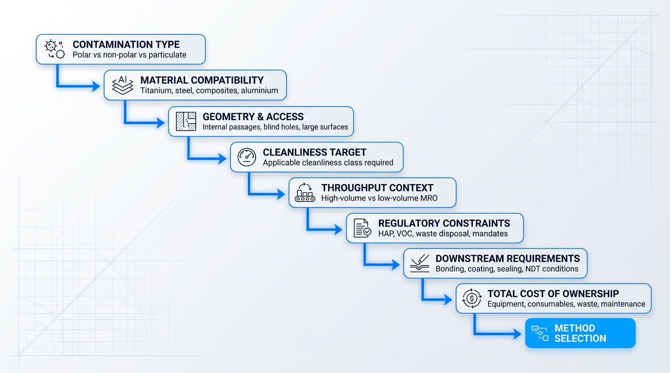
In practice, several criteria are often active simultaneously, and a single application may trigger constraints at multiple points in the sequence. The framework is a thinking tool, not a rigid algorithm — its value is in preventing the most common selection error, which is evaluating cleaning methods on cleaning performance alone while treating compatibility, compliance, and downstream requirements as secondary considerations.
No single aerospace cleaning method is universally optimal. The right choice emerges from matching contamination type, substrate, geometry, cleanliness target, downstream requirements, and operational context in sequence — and in most complex applications, the constraint that rules out an otherwise capable method is not what it removes, but what it leaves behind.
Where the framework points toward a dry, chemistry-free method — particularly for applications with tight downstream process requirements, compliance-constrained facilities, or high-volume production lines — laser cleaning warrants serious evaluation. For portable, in-situ, and MRO applications, WSL's ELASER-RHZ brings a genuinely differentiated capability: WSL's patented world-first reduced hazard zone technology collapses the laser hazard zone, enabling cleaning in open workshops and mixed-use facilities without sealing off the area — something no other laser cleaner on the market can offer. It is CE and UKCA certified, chemical-free, and tunable across the full range of contaminant types and aerospace-compatible substrates including titanium and aluminium alloys.
For high-volume repetitive production cleaning, AutoLASE addresses the throughput criterion directly: load the part, and the system scans it, builds a 3D map, and generates the clean automatically — no manual programming, no path-setting, no knowledge of part geometry required. Every cycle holds the same cleaning standard without operator skill as a variable. With the optional RHZ upgrade, AutoLASE can be configured to operate without an enclosure — a capability no competitor can match. Both systems are competitively priced and backed by WSL as the only UK-based laser cleaning manufacturer, designing, building, and supporting its machines entirely in-house — not rebadging third-party equipment as many in the sector do.
Having the framework in hand is the first step; applying it to a specific programme, component, and operational context is where the real work begins. The conclusion draws together the guide's core decision criteria and points toward what that application process looks like in practice.
See Laser Cleaning Applied to Aerospace Components
The framework is clear — now see how laser cleaning performs in practice. The ELASER is a validated laser cleaning machine built for precision surface preparation on aerospace-grade components.
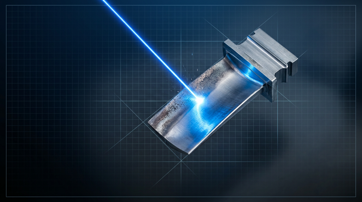
Conclusion
Putting it together: cleaning method selection in practice
The principle this guide has been building toward is straightforward: no single aerospace cleaning method is universally optimal. The right choice is always a product of context — contamination type, substrate, geometry, cleanliness target, downstream process, and operational constraints working together.
Environmental and worker safety considerations belong in that same calculation as structural constraints, not afterthoughts.
The practical next step is to consult the applicable standards for your specific component, engage cleaning technology specialists for process validation, and — where laser cleaning is under consideration — explore the portable and automated solutions now available for aerospace applications.
Frequently asked questions about aerospace cleaning
Common questions about aerospace cleaning processes, methods, standards, and professional roles — answered directly.
Aerospace cleaning follows a structured workflow rather than a single operation. The process begins by identifying the component, the contamination type present, and the applicable cleanliness standard. The appropriate cleaning method is then selected based on those inputs — substrate compatibility, contamination class, and downstream process requirements all factor into that choice. Cleaning takes place in a controlled environment using the selected method and chemistry. Once complete, cleanliness is verified using the required technique: particle count, non-volatile residue (NVR) measurement, contact angle testing, or visual inspection, depending on the standard. The process and results are documented to support airworthiness records, quality audit, and traceability requirements. Only then is the component returned to service or passed forward to the next assembly or maintenance stage.
There are five principal categories of aerospace cleaning method. Solvent/vapour degreasing uses solvent-based fluids — typically in a vapour degreaser — to dissolve non-polar organic contaminants such as machining oils and greases; it is well suited to complex geometries where water entrapment is a risk. Aqueous cleaning combines water with detergents, surfactants, and other additives to remove polar contaminants such as salts and oxidation residue; ultrasonic agitation is often applied to enhance penetration. Ultrasonic cleaning uses high-frequency pressure waves to generate cavitation implosions in a liquid medium, reaching blind holes, crevices, and intricate internal geometries that other methods cannot access reliably. Dry and abrasive methods — including dry ice blasting, CO2 snow cleaning, and laser cleaning — remove contaminants without liquid chemistry, leaving no residual cleaning agent on the surface. Mechanical cleaning covers abrasive techniques such as bead blasting, grit blasting, and wire brushing for surface preparation and heavy deposit removal. Method selection depends on the contamination type, substrate material, component geometry, and the cleanliness class required for the application.
An aerospace cleaning technician prepares components and assemblies for the cleaning operation, selects and applies the appropriate method and chemistry for the contamination type and substrate, then verifies that the required cleanliness level has been achieved using the applicable technique — particle count, NVR measurement, contact angle, or visual inspection. They document the process and results to support airworthiness records, quality audit, and traceability requirements. The role spans both manufacturing and MRO contexts. In manufacturing, technicians clean new components before assembly or bonding. In MRO, they clean in-service components during scheduled maintenance and overhaul — and the role regularly overlaps with inspection, since cleaning is a prerequisite for corrosion assessment, non-destructive testing, and return-to-service sign-off. The work requires practical knowledge of chemistry compatibility with aerospace materials, applicable cleanliness standards such as NAS 1638, IEST-STD-CC1246, and programme-specific requirements, as well as the documentation protocols that underpin regulatory compliance.
Yes — but "deep cleaning" means different things depending on context, and the distinction matters. At the most visible level, aircraft receive periodic exterior washing of fuselage and surfaces using approved cleaning agents; per FAA guidance, this forms part of a structured corrosion prevention and control programme, with washing intervals as frequent as every 15 days in severe operating environments. During scheduled MRO, internal systems — hydraulic circuits, engine components, avionics, fuel systems — are precision cleaned to documented cleanliness classes using methods and chemistries appropriate to each system. At heavy maintenance events (C-check or D-check level), the airframe interior, bilge areas, and structural zones receive comprehensive cleaning as part of corrosion inspection and structural assessment. In the aerospace precision sense, deep cleaning refers specifically to the precision cleaning of internal systems and components to a defined cleanliness class — not cosmetic or appearance cleaning. The methods, verification requirements, and documentation obligations differ fundamentally between the two. Cleaning schedules are driven by the manufacturer's maintenance manual, the operator's corrosion prevention programme, and applicable airworthiness requirements.
The applicable cleanliness standard is defined by the programme, system specification, or OEM maintenance manual — it is not chosen by the operator. Start with the programme-level contamination control plan or the system specification for the component in question. For hydraulic systems, NAS 1638 and SAE AS4059 cleanliness classes are the governing specifications; AS4059 was developed from NAS 1638 and the two are closely related, with AS4059 offering additional flexibility in how cleanliness classes are reported. For spacecraft and precision flight hardware, IEST-STD-CC1246 defines both particulate and non-volatile residue (NVR) cleanliness levels. For general aerospace hardware in manufacturing, the programme contamination control plan or the applicable AMS specification sets the requirement. For MRO and maintenance work, the OEM maintenance manual and the relevant FAA advisory circular define what is required. If the applicable standard is not clearly identified in those documents, the correct route is to consult the OEM or the applicable regulatory authority — not to make an independent judgement. Once the standard is confirmed, the cleaning method must then be validated against that cleanliness class for the specific application.
Yes. Laser cleaning has been validated for aerospace surface preparation and component cleaning in documented programmes. The U.S. Navy's Fleet Readiness Center East (FRCE) has tested laser ablation technology on aircraft support components, confirming its ability to safely remove corrosion and hazardous coatings without damaging the underlying substrate or generating hazardous mixed waste. In production, an Automated Structure Laser Cleaner (Auto SLC) system has been deployed on the F-35 wing line to remove primers and protective coatings, producing a surface quality suitable for mechanical bonding of nutplates — replacing manual sanding and solvent wiping. One practical advantage for cleanliness verification is that laser cleaning leaves no chemical residue. There is no residual cleaning agent to confound particle count or NVR measurements, which simplifies post-process verification. The honest qualification is that specific cleanliness class compliance depends on process parameters, substrate, contamination type, and the verification method applied. As with any cleaning method, the process must be validated against the applicable cleanliness standard for the specific application before it can be used in a controlled production or MRO context.