

Introduction
This list is for engineers and system architects actively evaluating 1550 nm EDFA hardware for real deployments — DWDM, CATV, FTTH, lab R&D, free-space optical communications, LiDAR, and sensing.
Every entry is a verified, commercially available amplifier or platform operating in the C-band (1530–1565 nm) window, sourced directly from manufacturers and authoritative distributor pages.
Each entry is assessed against the same seven axes: output power, gain, noise figure, C-band wavelength coverage, control modes and interfaces, form factor, and application fit — including RS-232, USB, Ethernet, and SNMP support, which varies more than most catalogue pages let on.
TL;DR
No single 1550 nm EDFA suits every deployment. Power range, noise figure, wavelength coverage, and control interface support differ substantially across the options here — and the gap between a well-matched amplifier and a convenient catalogue pick shows up quickly in the field.
The right choice depends on matching each axis to your specific application, not just the headline output figure.
This article covers:

Output power, gain, and noise figure compared
C-band wavelength coverage and L-band availability
Control interfaces: RS-232, USB, Ethernet, SNMP
Form factor: module, benchtop, and rack-mount
Application fit: DWDM, LiDAR, FTTH, and lab
Customisation depth and manufacturer vs. reseller
How to Evaluate a 1550 nm EDFA
Not all 1550 nm EDFAs are the same — and the headline spec sheet rarely tells the whole story. The axes below are the ones that separate a well-matched amplifier from one that causes problems six months into deployment.
- Output power and scalability: Saturated output power figures can mislead: actual delivered power depends on input conditions. For high-power applications, treat the full configurable power range as a primary filter, not the headline dBm figure.
- Gain and noise figure: Gain sets amplification depth; noise figure (NF) sets the SNR degradation the amplifier introduces. NF matters most in cascaded chains and preamplifier roles, where noise accumulates across every stage.
- C-band wavelength coverage: The standard EDFA gain window runs 1530–1565 nm, but some catalogue units cover only the red C-band (1540–1563 nm). Verify the exact operating window before assuming full C-band coverage.
- Control modes and interfaces: APC maintains constant output power by adjusting the pump; AGC maintains constant gain. For deployed DWDM or CATV infrastructure, NMS integration via Ethernet or SNMP is a standard requirement.
- Form factor: Module formats suit OEM integration; benchtop suits lab R&D; rack-mount suits deployed network infrastructure. The right choice is determined by deployment context, not performance preference.
- Connectors and lead times: Ask vendors about connector type, patch-cord options, and key width before ordering — these details vary by configuration. Ask about current lead times too, especially for made-to-order units.
Two of these axes are consistently underserved in vendor literature, and both are worth investigating before you shortlist.
Manufacturer vs. reseller: ask the question directly
A vendor who designs and manufactures in-house can offer genuine engineering support, adapt a design post-delivery, and stand behind a specification they created themselves.
Resellers and importers typically cannot offer this depth — they can fulfil a catalogue order, but they cannot modify the product or provide the engineering dialogue that demanding applications require. Ask any vendor directly: do you design and manufacture this unit?
Customisation depth: catalogue vs. engineered-to-requirement
A fixed-catalogue EDFA is a sound choice when the published specification matches the requirement off the shelf — there is no premium worth paying for customisation you do not need.
For non-standard applications — high average power, unusual pulse regimes, bespoke form factors, or specific control interfaces — a platform engineered to the requirement will outperform a catalogue unit adapted to fit. The practical question is whether the vendor's platform can be configured to your requirement, or whether you are being sold the closest available approximation.
In a cascaded amplifier chain, any noise the amplifier introduces is magnified by every subsequent stage. This makes NF a more consequential differentiator than it appears in a single-unit comparison — particularly in long-haul links and preamplifier roles where inline noise accumulates across the full span.
With these axes in mind, the entries below can be read as a structured comparison rather than a catalogue — each one assessed against the same framework.
Product 1
Woodrow Scientific Custom EDFA

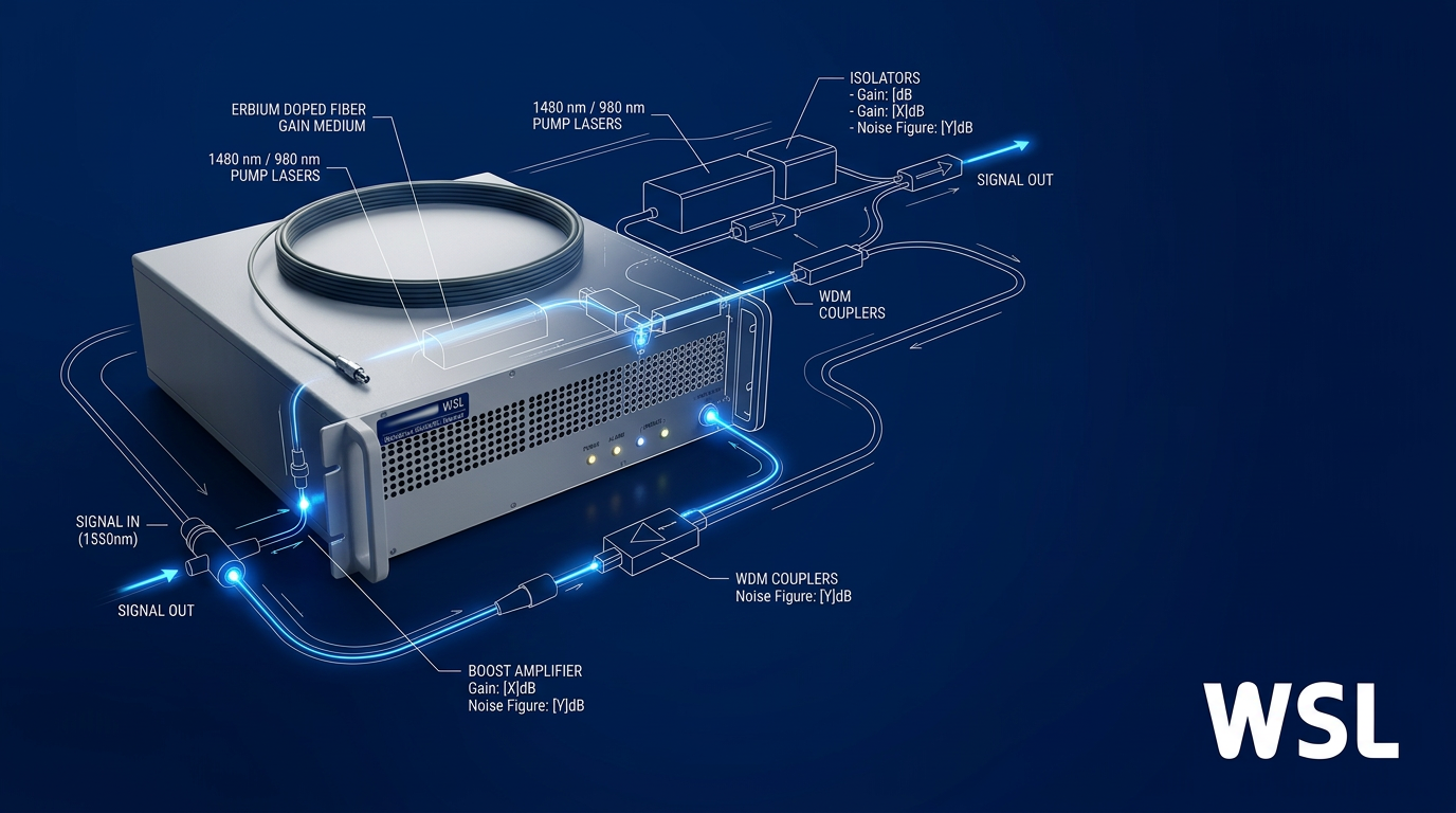
A bespoke MOPA erbium-doped fibre amplifier built end-to-end to your application — band, power, pulse regime, firmware, and form factor all configured per project, scaling to 200 W or more.
Pros:

Fully configurable: band, power, firmware, form factor
Scales to 200 W or more average power
C-band and L-band from one cable
In-house UK manufacturer with direct engineering support
Cons:

No off-the-shelf pricing; quote required
Gain and NF not fixed specs
Woodrow Scientific (WSL) is a UK manufacturer of erbium-doped fibre amplifiers, designing, building, qualifying, and supporting every unit in-house from its Southampton facility — the city where the EDFA was invented, at the Optoelectronics Research Centre.
That provenance matters in practice: WSL's engineering team works directly with customers through integration, and because the amplifier is built in-house on patented technology, post-delivery adaptability is a real option rather than a support-desk conversation with a reseller.
End-to-End Customisation
The defining characteristic of the WSL platform is the depth of per-project configuration available — not a choice of catalogue variants, but a unit engineered from the ground up to the customer's specification.
Every parameter in the following list is configured per project, with the erbium physics and MOPA architecture as the only fixed foundations.
- Operating band: C-band, L-band, or dual C+L — specified per project.
- Output power: From low-power builds (e.g. 5 W) to 200 W or more average power; fully controllable from 0–100% of rated output.
- Pulse regime: CW, short-pulse (e.g. 100–500 ns), or custom — including pulse energies above 10 mJ and peak powers above 100 kW.
- Cooling: Air-cooled as standard, requiring no chiller or coolant loop; water cooling available as an option.
- Delivery cable: Length and termination configured per project.
- Form factor: Custom integration envelope to match the deployment context.
- Control firmware and comms: RS-232, Ethernet, SNMP, or bespoke — WSL builds the control interface to the buyer's requirements.
This level of tailoring is what separates a purpose-built amplifier from a catalogue part, particularly for demanding deployments where the integration envelope, thermal management, or control interface cannot flex to meet a fixed-spec product.
Output Power and Scalability
WSL builds to 200 W or more average power — the highest commercially available for erbium-doped fibre amplifiers — with output continuously controllable from 0 to 100% of rated power.
For pulsed applications, the platform supports pulse energies above 10 mJ and peak powers above 100 kW, making it viable for demanding short-pulse work that fixed-catalogue amplifiers rarely reach.
Gain, Noise Figure, and MOPA Architecture
WSL does not publish fixed gain or noise figure values, because both are engineered to the application rather than drawn from a standard specification sheet.
Buyers specify their gain and noise figure requirements as part of the project brief; WSL's engineers optimise the gain medium within the MOPA architecture accordingly — a more accurate representation of capability than a fixed NF figure that may not reflect the actual operating condition.
Wavelength Coverage: C-Band and L-Band
The platform covers the full 1530–1625 nm window, spanning C-band (1530–1565 nm) and L-band (1565–1625 nm).
Crucially, both bands are available from a single source through one cable — no second amplifier, no additional integration complexity.
C-band and L-band amplification from one WSL unit through a single cable eliminates the need for a second amplifier in dual-band deployments, reducing integration overhead and potential failure points.
Form Factor, Cooling, and Certifications
Every WSL unit is built to a custom integration envelope, so the form factor is not a constraint the buyer works around — it is a parameter they specify.
Air cooling is standard, meaning no chiller or coolant loop is required and integration is straightforward; water cooling is available for deployments where it is preferred.
Units are CE and UKCA certified and ship worldwide direct from WSL.
Eye-Safe 1550 nm Operation
The 1550 nm wavelength carries a significantly higher eye-damage threshold than 1064 nm sources, a practical advantage in applications where personnel work in proximity to the beam.
WSL offers reduced-hazard-zone builds for deployments where minimising the laser safety exclusion area is a design requirement.
Application Fit
The platform's configurable nature means application fit is broad — the list below reflects illustrative deployments, not a closed set.
- LiDAR: Eye-safe high-power amplification for LiDAR systems.
- Free-space optical communications (FSOC): Ground-station uplink and beacon amplification — the EDF-UL-10 is an illustrative build for this application.
- Short-pulse applications: High peak-power pulsed amplification — the EDF100 is an illustrative build for this regime.
- Defence and directed-energy research: High-power fibre amplification for directed-energy and defence R&D programmes.
- Quantum sensing and communications: Precision amplification in the 1550 nm window for quantum photonics applications.
- Fibre sensing (DAS / structural): Amplification for distributed acoustic sensing and structural health monitoring.
- Remote sensing and scientific instrumentation: Tailored amplifiers for laboratory, field, and research instrument integration.
If an application requires a high-power, eye-safe 1550 nm erbium-fibre amplifier, WSL's engineers assess each requirement individually — the platform is not limited to the use cases listed above.
Woodrow Scientific Custom EDFA: Key Specifications
| Axis | WSL Custom EDFA |
|---|---|
| Architecture | MOPA (master oscillator power amplifier) |
| Gain medium | Erbium-doped fibre |
| Wavelength window | 1530–1625 nm (C-band + L-band) |
| Average output power | Configurable — up to 200 W or more |
| Pulse energy | Configurable — above 10 mJ available |
| Peak power | Configurable — above 100 kW available |
| Power control | 0–100% of rated output |
| Gain | Configured per project |
| Noise figure | Configured per project |
| Cooling | Air-cooled standard; water cooling optional |
| Control interfaces | Configured per project (RS-232, Ethernet, SNMP, bespoke) |
| Form factor | Custom integration envelope per project |
| Certifications | CE, UKCA |
| Manufacture | Southampton, UK (in-house) |
| Pricing | Quote-based |
Key specification axes for the Woodrow Scientific Custom EDFA. Gain and noise figure are configured per project and are not published as fixed values.
To specify a unit, buyers submit their requirements directly to WSL for a specialist evaluation — the starting point is the application, not a catalogue page.
Product 2
Thorlabs EDFA Series: Benchtop and PXIe Module
Turnkey C-band EDFAs from Thorlabs, available as benchtop units or PXIe plug-in modules, with fixed catalogue specifications across the EDFA100 and EDFA300 families — suited to lab R&D and test and measurement.
Pros:
Published fixed specs: no ambiguity before ordering
Dual form factor: benchtop and PXIe module
SM and PM fibre variants available
Low dispersion design suits ultrafast pulse work
Cons:
C-band only (1530–1565 nm)
Output power ceiling below high-power applications
Operating temperature range limits field deployment
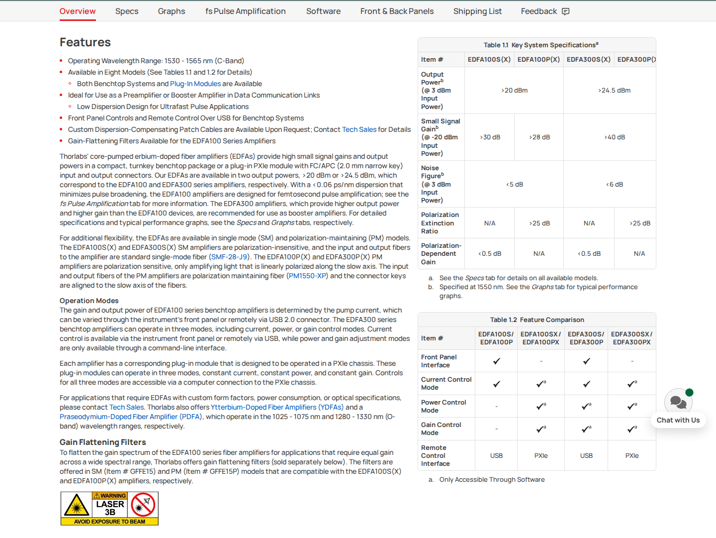
Thorlabs' EDFA100 and EDFA300 series are core-pumped, turnkey 1550 nm erbium-doped fiber amplifiers offered in two distinct form factors: benchtop systems and PXIe 2-slot plug-in modules.
The two series differ primarily in output power and gain ceiling, with both available in single-mode (SM) and polarisation-maintaining (PM) fibre variants, and each form factor carrying the same optical performance as its counterpart.
EDFA100 vs EDFA300: Performance at a Glance
The table below shows the key performance figures for both series, tested at the stated input power conditions published on the Thorlabs product pages.
| Specification | EDFA100S (SM) | EDFA100P (PM) | EDFA300S/P |
|---|---|---|---|
| Saturated Output Power (@ 3 dBm input) | >20 dBm | >20 dBm | >24.5 dBm |
| Small-Signal Gain (@ -20 dBm input) | >30 dB | >28 dB | >40 dB |
| Noise Figure (@ 3 dBm input) | <5 dB | <5 dB | <6 dB |
| Total Dispersion Within Amplifier | <0.06 ps/nm | <0.06 ps/nm | <0.14 ps/nm |
| Operating Wavelength | 1530–1565 nm | 1530–1565 nm | 1530–1565 nm |
Output power, small-signal gain, noise figure, and total dispersion for the EDFA100 and EDFA300 series, drawn from Thorlabs' published product specifications.
The EDFA300 series delivers higher output power and significantly higher small-signal gain than the EDFA100, making it the stronger candidate for booster amplifier roles in data communication links.
The EDFA100's low total internal dispersion is the standout figure for ultrafast pulse work — Thorlabs describes this series as designed for femtosecond pulse amplification, with dispersion-compensating patch cables available on request.
Both series cover the 1530–1565 nm C-band window, which is the relevant scope boundary for readers evaluating L-band or dual-band requirements.
Control Modes by Variant
Control capability varies across variant types and is worth mapping carefully for readers integrating these amplifiers into automated test environments.
- EDFA100 Benchtop: Constant current mode, via front panel controls or remote USB connection.
- EDFA100 PXIe Modules (EDFA100SX / EDFA100PX): Constant current, constant power, and constant gain modes, controlled via computer connection to a PXIe chassis.
Readers working in PXI-based test systems will note that the EDFA100 PXIe module variants add constant power and constant gain modes beyond what the EDFA100 benchtop supports — a material capability difference for automated measurement workflows.
Form Factor and Operating Conditions
The benchtop units run from mains voltage (100–240 VAC), while the PXIe modules draw power from the chassis — a practical distinction for lab infrastructure planning.
All variants use FC/APC connectors with 2.0 mm narrow key on both input and output ports, with SM variants using SMF-28-J9 fibre and PM variants using PM1550-XP.
Operating temperature ranges differ between series and are a meaningful constraint for deployment context: the EDFA100 series is rated for 15–35 °C, while the EDFA300 series is rated for 15–30 °C. Both ranges are consistent with controlled laboratory environments.
Application Fit
These amplifiers are well suited to lab R&D, test and measurement, component characterisation, preamplifier or booster roles in data communication links, and ultrafast pulse applications where dispersion control is critical.
The output power ceilings across both series place them outside the scope of high-power applications, and the operating temperature constraints limit use outside controlled environments.
Thorlabs EDFA Pricing
Current pricing is available directly from the Thorlabs website or by contacting Thorlabs' sales team.
Product 3
Keopsys (Lumibird) CEFA Series
A broad CW EDFA family from Lumibird (Keopsys), spanning C-band and L-band, high-gain metrology models to high-power scientific units up to 43 dBm, available as benchtop or OEM module.
Pros:
CEFA-C-HG: 50 dB gain, near quantum-limited NF
Wide family: metrology to high-power scientific
C-band and L-band sub-series available
PM options across range, including at 43 dBm
Cons:
Fixed catalogue builds; not bespoke per project
C-band and L-band are separate product lines
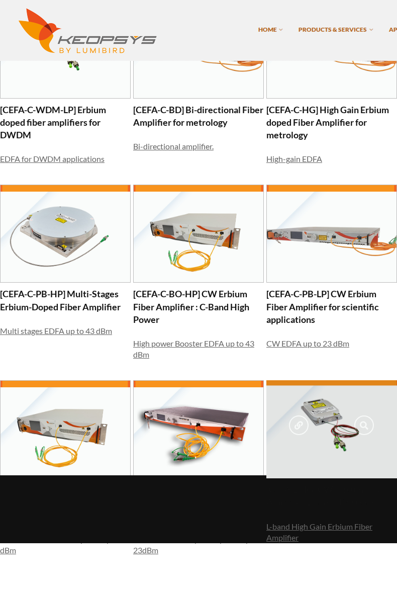
The Keopsys CEFA series, marketed under the Lumibird brand (Keopsys is the Lumibird subsidiary), is one of the broadest catalogue EDFA families commercially available, spanning ten distinct sub-models across C-band and L-band, from high-gain metrology amplifiers to high-power scientific and industrial units.
Unlike narrower catalogue ranges, the CEFA family is structured so that different sub-series address genuinely different engineering requirements — the choice of model is driven by application, not just output power.
Output Power Range Across the CEFA Family
Output power spans a wide range across the family, from standard scientific models up to high-power units that Keopsys lists at up to 43 dBm.
| Model | Band | Max Saturated Output | Form Factor |
|---|---|---|---|
| CEFA-C-PB-LP | C-band | 23 dBm | Benchtop or OEM module |
| CEFA-C-WDM-LP | C-band | 23 dBm | Benchtop or OEM module |
| CEFA-C-PB-HP | C-band | 43 dBm | Benchtop or OEM module |
| CEFA-C-BO-HP | C-band | 43 dBm | Benchtop or OEM module |
| CEFA-L-PB-LP | L-band | 23 dBm | Benchtop or OEM module |
| CEFA-L-PB-HP | L-band (1565–1605 nm) | 37 dBm | Benchtop or OEM module |
Output power and form factor across the main CEFA sub-series, as listed on Keopsys/Lumibird product pages.
The CEFA-C-PB-HP is a multi-stage C-band amplifier that accepts input signals down to -20 dBm and delivers up to 43 dBm, with polarisation-maintaining options available even at maximum output power.
The CEFA-C-BO-HP is a distinctive variant: it delivers its output as a free-space beam rather than a fibre-coupled signal, with Keopsys specifying beam quality of M² less than 1.1 — a characteristic relevant to sensing and focusing applications.
CEFA-C-HG: High-Gain Series
The CEFA-C-HG is the family's most technically differentiated model and the one on which the CEFA range most clearly leads relative to typical catalogue EDFAs.
Keopsys describes the CEFA-C-HG as designed to amplify very weak optical signals down to -50 dBm input, with small-signal gain up to 50 dB and a noise figure characterised as near quantum-limited. Polarisation-maintaining options are available in both 40 dB and 50 dB gain configurations.
Keopsys lists quantum cryptography, optical metrology, optical remote sensing, and test and measurement among the CEFA-C-HG's target applications.
The all-fibre design eliminates free-space alignment, and Keopsys states the device is available in both benchtop (front-panel or RS-232/RJ45 with SNMP) and compact OEM module formats.
Wavelength Coverage: C-Band and L-Band
The CEFA family covers both C-band (CEFA-C sub-series) and L-band (CEFA-L sub-series) as separate product lines, each available in its own benchtop or OEM module configuration.
The CEFA-L-PB-HP operates from 1565 to 1605 nm, with extended ranges available on request according to Keopsys.
Control Interfaces and Operating Modes
Interface options vary by model and power level across the family, with RS-232, USB, and RJ45 all represented in the catalogue.
- CEFA-C-PB-HP benchtop: Front-panel control or RS-232/USB; RJ45 interface available for models below 33 dBm output.
- CEFA-C-PB-LP benchtop: RJ45 interface for network control; compact OEM module available.
- CEFA-C-HG benchtop: Front-panel, RS-232, or RJ45 with SNMP; compact OEM module also available.
- OEM module variants (general): Controlled via RS-232 across the range; designed for integration into complex optoelectronic systems.
Keopsys lists a low noise figure among the key features of the CEFA-C-PB-HP, alongside an excellent optical signal-to-noise ratio at the output.
Application Fit by Sub-Series
The breadth of the CEFA family maps directly to a wide spread of application contexts, with Keopsys positioning each sub-series against distinct use cases.
- CEFA-C-HG: Optical metrology, quantum cryptography, optical remote sensing, high-sensitivity preamplification — where very low input power and near quantum-limited noise figure are the primary requirements.
- CEFA-C-PB-HP: Scientific applications including atomic cooling, quantum optics, nanotechnologies, material characterisation, non-linear optics, and microwave optics.
- CEFA-C-BO-HP: Remote sensing (LIDAR), non-linear optics, optical component testing — applications where free-space beam output and high beam quality are advantageous.
- CEFA-C-WDM-LP: Dense wavelength division multiplexing (DWDM), regional and metro networks, FTTH/CATV, and free-space communication — with dynamic gain control for optimum gain flatness across multiple channels.
- CEFA-L-PB-HP: L-band DWDM transmission, free-space communication, LIDAR, biotechnologies, and material characterisation — covering the 1565–1605 nm window.
The CEFA family's catalogue structure means models are selected from a defined range rather than engineered to a per-project specification — a straightforward trade-off between breadth of choice and the depth of customisation available from bespoke EDFA suppliers.
Need an EDFA Built to Your Specification?
Woodrow Scientific designs and builds custom 1550 nm EDFAs in-house, configured to your band, power level, and form factor. Off-the-shelf catalogues have limits — a bespoke build does not.

Product 4
Nuphoton Technologies EDFA Range
A US-manufactured catalogue of compact C-band EDFA modules and rack-mount units, spanning +17 to +37 dBm output across discrete models, with RS-232 control and published datasheets suited to OEM integration.
Pros:
Compact modules down to 71 × 43 × 12 mm
Wide output power span: +17 to +37 dBm
Published datasheets with verified specs per model
Space-qualified variant available for LEO/MEO/GEO
Cons:
Fixed catalogue specs; not configurable per project
Pricing not published; requires direct enquiry
Most models C-band only (1530–1565 nm)
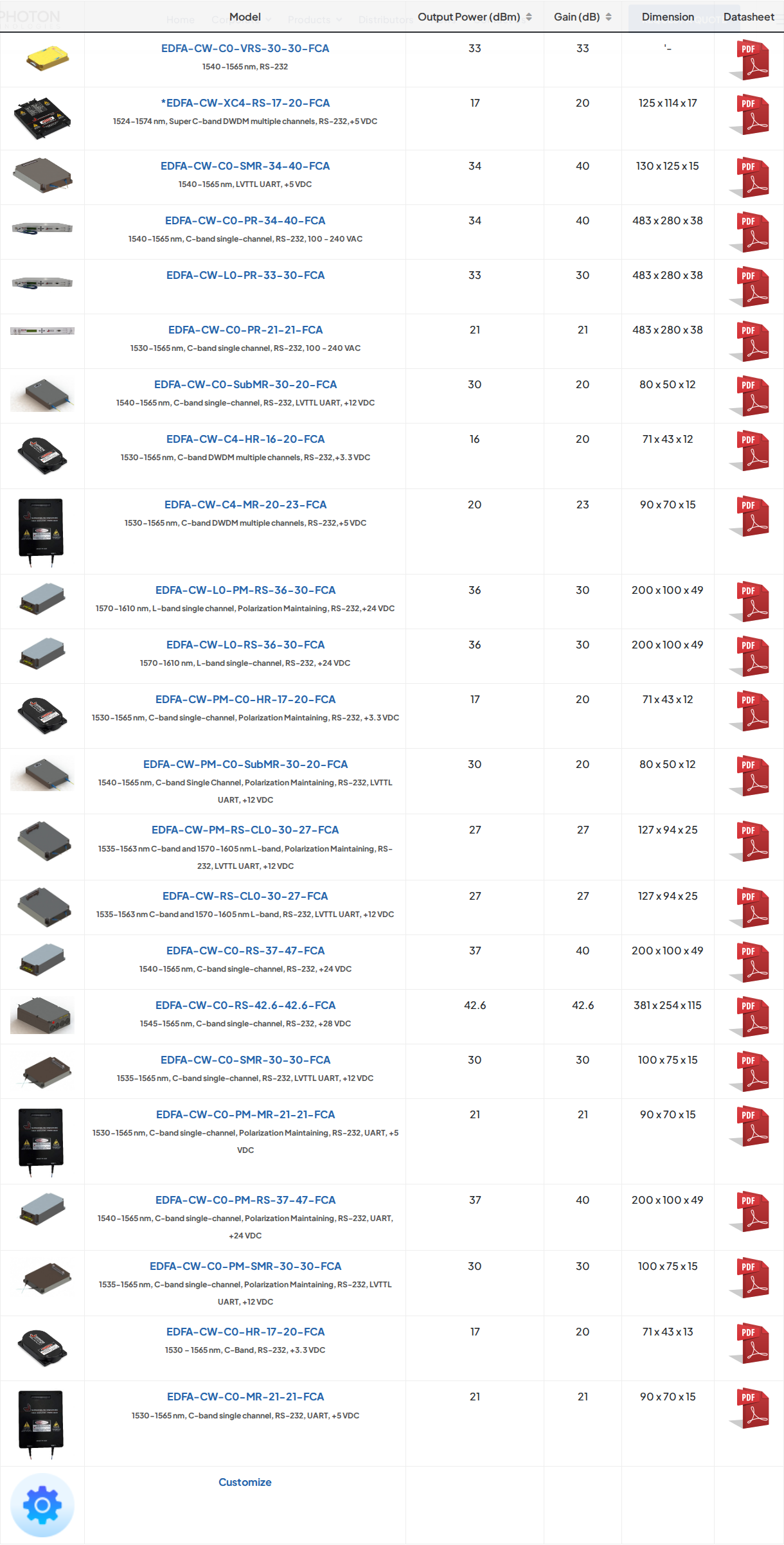
Nuphoton Technologies, based in Murrieta, California, manufactures a catalogue of C-band erbium-doped fibre amplifiers spanning compact OEM modules through to rack-mount units, with published datasheets covering output power, gain, noise figure, dimensions, and interface specifications for each model.
The range's clearest differentiator is its module footprint: the EDFA-CW-C0-HR-17-20-FCA measures just 71 × 43 × 12 mm, and the SubMR-30 model measures 80 × 50 × 12 mm — both running from low-voltage DC supplies, which makes them well-suited to board-level and system integration.
Nuphoton EDFA Key Specifications by Model
The table below summarises key specifications across six models in the Nuphoton catalogue.
| Model | Output Power | Gain | Noise Figure | Wavelength | Dimensions (mm) |
|---|---|---|---|---|---|
| EDFA-CW-C0-HR-17-20-FCA | +17 dBm | 20 dB | ≤5.5 dB | 1530–1565 nm | 71 × 43 × 12 |
| EDFA-CW-C0-MR-21-21-FCA | +21 dBm | 21 dB | ≤5.0 dB | 1530–1565 nm | 90 × 70 × 15 |
| EDFA-CW-C0-SubMR-30-20-FCA | +30 dBm | 20 dB | – | 1540–1565 nm | 80 × 50 × 12 |
| EDFA-CW-C0-SMR-34-40-FCA | +34 dBm | 30–40 dB | ≤6.0 dB | 1540–1565 nm | 130 × 125 × 15 |
| EDFA-CW-C0-PR-34-40-FCA | +34 dBm | 40 dB | ≤6.0 dB | 1540–1565 nm | 483 × 280 × 38 |
| EDFA-CW-C0-PM-RS-37-47-FCA | +37 dBm | – see text | ≤6.5 dB | 1540–1565 nm | 200 × 100 × 49 |
Key specifications across six Nuphoton EDFA models. All models use FC/APC connectors with SMF-28 fibre; the PM-RS-37 uses PM fibre. – indicates the noise figure is not published for that model. – see text: gain for the PM-RS-37 model is attributed in the text below.
The EDFA-CW-C0-SMR-34-40-FCA stands out within the module sub-range for its 30–40 dB adjustable gain at +34 dBm output — the only model in the catalogue with a published variable gain range rather than a fixed gain point.
Nuphoton's published datasheet for the PM-RS-37 model (EDFA-CW-C0-PM-RS-37-47-FCA) states a gain of 47 dB; the model's product page states 40 dB. The PM-RS-37 also carries a polarisation extinction ratio of ≥20 dB, making it relevant for polarisation-sensitive system architectures.
Control Modes and Interface
RS-232 is the standard control interface across the catalogue, present on every model from the 71 mm compact module to the 19-inch rack-mount unit.
Most models support both AOPC (constant output power) and ACC (constant pump current) operating modes; the SubMR-30 and PM-RS-37 models operate in ACC mode only, as stated on their respective product pages.
The SubMR-30 and SMR-34 module variants also expose an LVTTL UART interface directly from the unit, alongside RS-232 — a detail relevant to embedded integration where RS-232 voltage-level translation would otherwise be required.
The rack-mount PR-34 model adds front-panel control alongside RS-232, which is consistent with its 19-inch form factor and infrastructure deployment context.
Application Fit
Nuphoton's product pages list applications including optical telecom booster and in-line amplification, fibre optic sensing, test and measurement, and laboratory R&D across the compact module range.
The catalogue also includes a DWDM-capable model (EDFA-CW-C4-HR-16-20-FCA), covering 1530–1565 nm across multiple C-band channels at +16 dBm output and 20 dB gain in the same 71 × 43 × 12 mm footprint as the single-channel HR-17.
Notably, the catalogue includes the EDFA-CW-RS-CL0-30-27-FCA, a combined C+L band module covering 1535–1563 nm (C-band) and 1570–1605 nm (L-band) at +27 dBm output — which separates Nuphoton from a strictly C-band characterisation of the range.
Nuphoton lists a space-rated EDFA designed for LEO, MEO, and GEO orbital environments. The company's space-qualified fibre amplifiers page states that its LEO EDFA delivers over 40 dB of optical gain and 5 W of output power from a single vacuum-ready module, with applications in satellite laser communications and precision LiDAR.
The EDFA-CW-C0-VRS-30-30-FCA, listed on Nuphoton's site with flight heritage across multiple short missions, operates across −10 to +55 °C in vacuum conditions (≤7.5 × 10⁻⁵ torr by design) — a specification profile distinct from the standard commercial module range.
Nuphoton EDFA Pricing
Pricing is not published on Nuphoton's product pages; prospective buyers should contact Nuphoton directly at their Murrieta, California facility for pricing and availability information, including for international orders.
Product 5
Agiltron EDFA Range
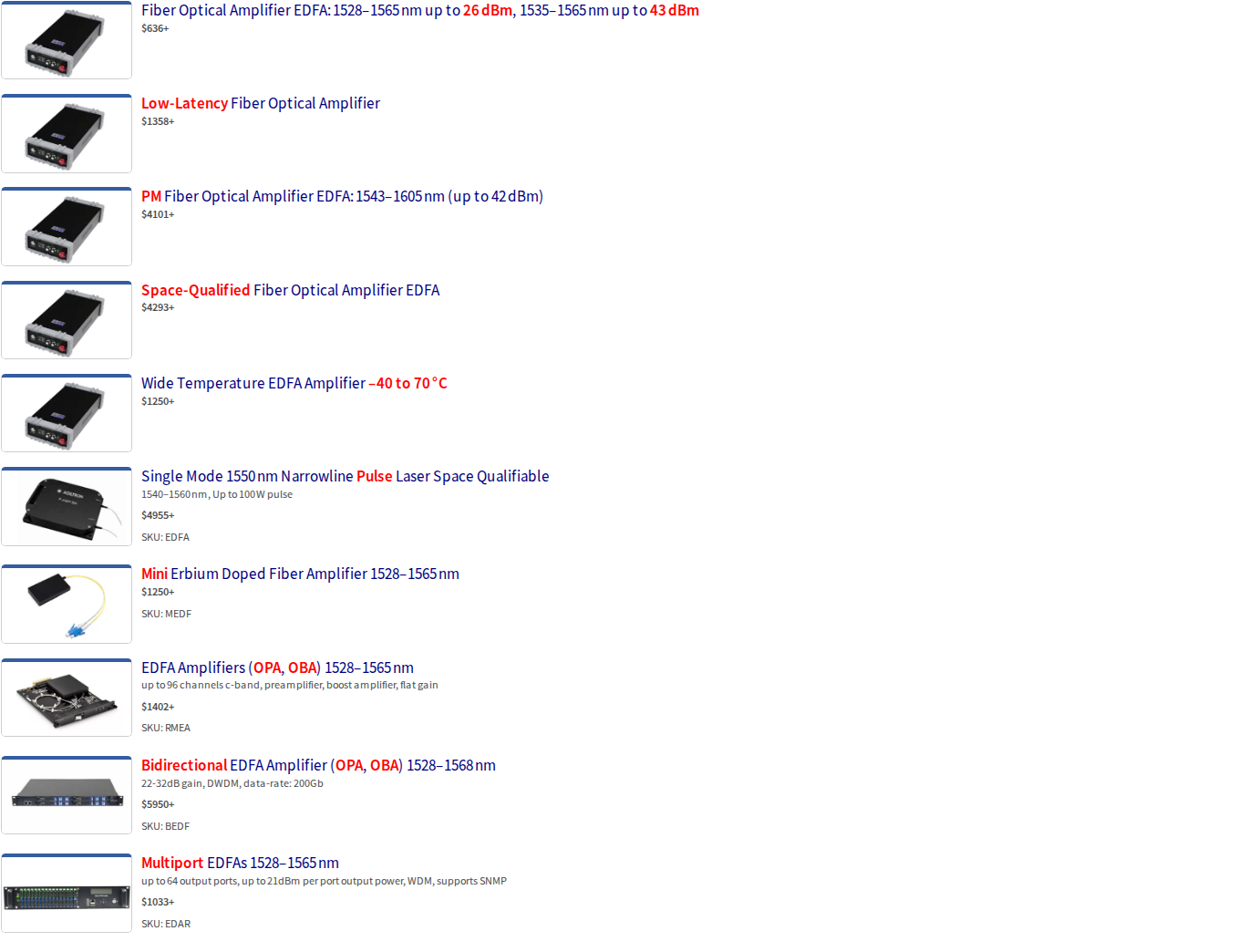
A US-based C-band EDFA range spanning booster and pre-amplifier units, a pulsed amplifier for LiDAR and sensing, and a multiport SNMP-enabled FTTx series, with an extended operating temperature option across the line.
Pros:
Booster output up to 41 dBm
Dedicated pulsed EDFA-P for LiDAR and sensing
EDAR multiport: up to 64 ports with SNMP
Pricing listed publicly on Agiltron's website
Cons:
High-power models narrow to 1535–1565 nm
No published Ethernet NMS integration beyond SNMP
Extended temperature range carries additional cost
Agiltron, based in the United States, manufactures a broad catalogue of 1550 nm erbium-doped fiber amplifiers spanning standard C-band booster and pre-amplifier units, a dedicated pulsed amplifier for LiDAR and sensing applications, and a multiport rack-mount series built for FTTx network infrastructure.
The range is notable in this list for two characteristics that appear in no other entry: a purpose-built pulsed EDFA variant and a multiport SNMP-managed amplifier chassis — both available as catalogue products with published pricing.
Performance and Specifications
The standard EDFA datasheet lists booster output power up to 41 dBm and pre-amplifier output power up to 25 dBm, with optical gain of up to 40 dB for both configurations.
Standard models operating below 25 dBm cover 1528–1565 nm; higher-power versions operate within 1535–1565 nm.
The Mini EDFA (MEDF) covers 1528–1565 nm and offers the broadest wavelength window in the standard range, making it the variant to note where full lower-C-band coverage matters.
The EDFA-P pulsed amplifier operates from 1540 to 1560 nm and delivers peak pulse output power up to 100 W, with pulse widths from 10 to 200 ns and repetition rates from 5 to 20 kHz.
The EDAR multiport series covers 1540–1560 nm, with per-port output power ranging from 17 to 23 dBm across configurations of 4 to 64 output ports, and a noise figure of 4.5 dB at 6 dBm input power per the MultiC EDFA datasheet.
| Product Line | Wavelength | Output Power | Ports / Config | Noise Figure |
|---|---|---|---|---|
| Standard EDFA (Booster) | 1535–1565 nm (>25 dBm); 1528–1565 nm (<25 dBm) | Up to 41 dBm | Single output | – |
| Standard EDFA (Pre-amp) | 1540–1565 nm | Up to 25 dBm | Single output | – |
| EDFA-P (Pulsed) | 1540–1560 nm | Up to 100 W peak | Single output | – |
| EDAR Multiport | 1540–1560 nm | 17–23 dBm per port | 4–64 ports | 4.5 dB (@ 6 dBm input) |
Key published specifications across the three main Agiltron EDFA product lines. – not publicly listed.
Agiltron's C-band EDFA category page states that the range offers an extended operating temperature of -25 to 70 °C, with the standard operating range being -5 to 40 °C and the extended range available at additional cost.
Control Interfaces and Form Factors
The standard EDFA supports ACC (Automatic Current Control) and APC (Automatic Power Control) modes, with USB and RS-232 communication interfaces; benchtop units include a computer control interface and GUI.
Three form factors are available for the standard EDFA: a benchtop unit, a compact OEM module, and a pluggable rack-mount configuration with an associated net-control rack.
The EDFA-P module variant uses RS-232 serial communication via a DB9 female connector, with module dimensions of 125 × 150 × 31.5 mm and benchtop dimensions of 255 × 285 × 115 mm. Agiltron's pulsed EDFA datasheet notes a space-qualifiable version is available.
The EDAR multiport series is housed in a 19-inch rack-mount chassis available in 2U, 3U, and 4U configurations, with redundant power supplies and SNMP support as standard features.
For buyers integrating the EDAR into managed network infrastructure, SNMP support covers the standard NMS integration path for FTTx and RF video overlay deployments. Beyond SNMP, no published Ethernet-based NMS integration is listed for the multiport series.
Application Fit
Agiltron's own product pages describe the following application fits across the range.
- EDAR Multiport: FTTx networks and RF video overlay networks requiring SNMP-managed amplification across multiple output ports, including mid-sized municipal networks and large Tier 1 service provider deployments.
- EDFA-P Pulsed: Doppler LiDAR, fiber optic distributed sensing, and narrow-linewidth pulse amplification where nonlinear suppression is required.
- Standard EDFA: DWDM booster and pre-amplifier roles, supporting up to 96 channels at 50 GHz spacing in the OPA/OBA rack-mount variant.
The EDAR series also supports integrated CWDM splitters, enabling routing of 1310 nm and 1490 nm data streams alongside the amplified 1550 nm signal in FTTx architectures.
Agiltron EDFA Pricing
Agiltron lists pricing on its category page. Agiltron's C-band EDFA category page lists the Mini EDFA from $1,250, and the pulsed EDFA-P from $5,560. The OPA/OBA rack-mount series and EDAR multiport starting prices are also listed on Agiltron's category page, where figures vary by configuration and port count.
Conclusion
Choosing the right 1550 nm EDFA for your deployment
The first question to resolve is always output power: fixed-catalogue units serve a wide range of standard applications well, but the moment a requirement pushes beyond what off-the-shelf power levels can deliver, the shortlist narrows sharply.
The second is customisation depth — whether the deployment context, pulse regime, form factor, or control firmware can be matched from a catalogue, or whether the application demands a platform engineered specifically to it.
For requirements that push hardest on both axes, this page's recommendation is the Woodrow Scientific Custom EDFA: end-to-end customisation, the highest commercially available power levels, and in-house engineering support throughout.
Frequently asked questions about 1550 nm EDFAs
These questions address the practical evaluation and procurement considerations buyers most commonly raise about 1550 nm erbium-doped fibre amplifiers — from control mode selection and noise figure to connector compatibility and lead times.
ACC (Automatic Current Control) fixes the pump laser drive current — output power varies if input signal power changes. APC (Automatic Power Control) regulates pump drive to maintain constant output power regardless of input variation. AGC (Automatic Gain Control) maintains a constant gain ratio between input and output, regardless of signal level. For a stable lab or fixed-input test environment, ACC is often sufficient. Deployed DWDM and CATV systems with variable input loading typically need APC, which is the most common choice for booster and in-line amplifier roles. Cascaded multi-span links benefit from AGC: maintaining consistent gain per stage prevents gain transients from propagating through the chain and accumulating into system-level noise problems. Several amplifiers covered on this page — including models from Thorlabs, Nuphoton, and Agiltron — support multiple modes, so verify which modes are available for your specific configuration before ordering.
Typical noise figure (NF) for a 1550 nm EDFA runs from approximately 4 dB to 7 dB, depending on amplifier architecture, input power level, and operating regime. NF quantifies the optical signal-to-noise ratio (OSNR) degradation the amplifier introduces — a lower NF means less noise added per stage. NF matters most in two contexts. In a preamplifier role, the amplifier is the first gain stage after a weak or attenuated signal; its NF directly sets the system noise floor, so low-NF designs are critical here. In cascaded multi-span links, each amplifier's NF contribution accumulates — a difference of even 1–2 dB per stage compounds significantly across many spans. Near-quantum-limited NF (approaching the 3 dB theoretical minimum) is achievable in high-gain, low-power architectures, relevant for metrology and atomic physics applications. Higher-power amplifiers typically carry higher NF figures — an accepted engineering trade-off. For bespoke platforms, NF is specified per application rather than published as a fixed catalogue value. When evaluating any amplifier, request the NF specification at your expected input power level, since NF is input-power-dependent and a single headline figure may not reflect your operating conditions.
C-band coverage is not uniform across products. The full C-band runs from approximately 1530 to 1565 nm, but some catalogue units cover only a subset of that window. Buyers should verify the exact operating range before specifying — a unit with a narrowed window excludes the short-wavelength C-band channels, which matters for WDM systems using the full C-band channel plan. Among the products covered on this page, Thorlabs covers 1530–1565 nm; Nuphoton offers models at 1530–1565 nm depending on configuration. L-band (approximately 1565–1625 nm) becomes relevant when WDM channel counts have exhausted C-band capacity, when specific application wavelengths fall outside the C-band window, or for certain sensing and spectroscopy applications. Combining C and L bands effectively doubles the available transmission window — Nokia notes this is how operators expand capacity over existing fibre. C+L dual-band coverage from a single amplifier source through one cable eliminates the need for a second amplifier and separate band-splitting hardware, which is a meaningful system-level distinction. Ask vendors explicitly whether their platform supports C+L from a single output, or whether C and L are separate product lines requiring separate units.
FC/APC (FC connector with angled physical contact polish) is the most common connector type across 1550 nm EDFA products, with SMF-28 single-mode fibre as the standard fibre type. FC/APC is preferred over FC/UPC in amplifier applications because the angled polish reduces back-reflection — Corning's connector documentation confirms APC polish achieves reflectance of −65 dB or better, compared to −55 dB for UPC. Back-reflections into an amplifier can cause instability and OSNR degradation. Three things to check before ordering: Key width — Thorlabs documents that its FC/APC connectors use a 2.0 mm narrow key, while wide-key variants use a 2.2 mm key; using a narrow-key FC/APC connector in a wide-key mating sleeve allows rotation and causes coupling loss, so matching patch cords are essential. Fibre type — confirm SMF-28 compatibility, or whether a PM (polarisation-maintaining) fibre option is needed; several products on this page offer PM variants. Port count — multiport amplifiers such as the Agiltron EDAR series have multiple output ports; verify connector type and count per port before ordering patch cords. For application-engineered platforms, cable length and termination type are configurable parameters set during the requirements discussion rather than fixed in a datasheet.
Yes — 1550 nm operation carries a higher eye-damage threshold than 1064 nm. The physical basis is well established: at 1064 nm, the beam falls within the retinal hazard region (400–1400 nm), where the eye's optics focus incident light onto the retina. At 1550 nm, the wavelength falls outside that retinal hazard region — OSHA and NIST laser safety documentation both place the retinal hazard zone as 400–1400 nm, with wavelengths above 1400 nm absorbed by the cornea and lens rather than focused onto the retina. This means a higher irradiance level is required to cause injury at 1550 nm than at 1064 nm for a given exposure scenario, and the effective hazard zone for a given output power is smaller at 1550 nm. This is relevant for LiDAR, free-space optical communications, sensing, and field deployments where personnel may be near the beam. Some amplifier platforms are built specifically to support reduced-hazard-zone deployment requirements. That said, 1550 nm systems can still be high-power devices capable of causing injury, and wavelength alone does not determine safe operation. Consult the relevant laser safety standard for your jurisdiction — IEC 60825-1 in the UK and EU, ANSI Z136.1 in the US — and engage a qualified laser safety officer for your specific deployment.
A manufacturer designs, builds, qualifies, and supports its own amplifiers in-house. A reseller sources and sells products it did not design or build. The distinction has four practical consequences for EDFA procurement. Engineering support: a manufacturer's team understands the product at the design level — they can diagnose integration issues, adapt firmware, modify the unit post-delivery, or build a variant to a revised specification. A reseller cannot offer this depth because the design knowledge does not sit with them. Customisation: genuine customisation — adapting band, power, pulse regime, control firmware, or form factor — requires in-house design and manufacturing capability. A reseller can only offer what the original manufacturer will build, typically from a fixed catalogue. Long-term supply and support: a manufacturer controls its own supply chain and can commit to spares, repairs, and design continuity. A reseller's support capability depends on the original manufacturer's policies, which the buyer cannot control. Accountability: with a manufacturer, the vendor who sold the unit is the vendor who built it — one point of contact for both commercial and technical issues. A straightforward due-diligence question to ask any EDFA vendor: "Do you design and manufacture this amplifier in-house?" The answer will quickly clarify which category you are dealing with and what level of post-sale engineering engagement is actually available to you.
Lead times vary significantly across the market. Catalogue units held in stock can ship within days to a few weeks — the buyer selects a part number and receives a pre-built unit; lead time is inventory-dependent. Made-to-order catalogue units are fixed-spec parts built to order rather than held in stock; lead time is the build time for that configuration, typically shorter than a fully bespoke build. Bespoke and application-engineered platforms require a requirements discussion to define the specification before the build begins — lead time includes that engineering phase, not just the manufacturing time. Buyers specifying a bespoke platform should initiate the conversation early in their project timeline, not after the purchase decision. The requirements discussion itself adds value: it ensures the delivered unit is matched to the application rather than adapted from a nearest-fit catalogue part. Most vendors do not publish specific lead times, and published figures may not reflect current demand or component availability in any case. The practical advice is to ask vendors directly about current lead times for your specific configuration at the earliest evaluation stage. For time-critical programmes, this conversation belongs in the evaluation phase, alongside the technical specification work.